text-indent: 2em; margin-top: 0px; margin-bottom: 0px; -ms-text-justify: inter-ideograph;">allow 0
where min qf is the minimum SF volume ratio,% and Wallow is limited calculated crack width. The calculation is based on the ����r�CW���� relationship or on the equivalent ����r�Ce���� one. The corresponding minimum SF volume ratio values based on [12,14] are given in Table 2.
5. Calculation of SF volume ratio as a function of required section��s ductility
As in usual RC elements, after the minimum SF volume ratio is obtained, it is necessary to calculate the design one. The main principals for this design are
�C by analyzing results of experimental investigations [1,3,7�C9,17,18], it can be concluded that SF in a bending pre-stressed section compressed zone add plastic defor-
 Concrete class Elastic stage deflections (mm)
Ultimate deflections (mm)
mations, ec f, after the ec2 value in a concrete matrix was achieved (see Fig. 3 below);
C140 8 44
C140 SF1% 7 84
C200 9 33
C200 SF2.4% 8 59
[1] the additional plastic deformations, ec f, should be calcu- lated as a function of the required section ductility, lreq, which, in turn, is given as a design parameter;
[2] the total value of the additional plastic deformations
 C200 SF2.4%/ C40
12 71
(taking into account the fibers confining effect) should be less then or equal to those without fibers [15]:
I. Iskhakov, Y. Ribakov / Materials and Design xxx (2007) xxx�Cxxx 5
ecf 6 ec2 ð15Þ
�C SF volume ratio is assumed to be a linear function of the required ductility.
Eq. (15) limits the maximum value of the additional plastic deformations, ec f. It is important to limit also their minimum value. According to relation (14), it should corre- spond to the minimum SF volume ratio, min qf. As it was mentioned above, if cracks appear in the concrete matrix, then fibers, added according to the min qf value, can take the transverse tensile strains. In this case
r
 rf max
rf
rf min
0
mHSC
mreq
mreq min
mreq max
min ecf ¼
ect ul
m
12 10��5

 ¼ 0:2
¼ 0:2
¼ 0:6 X 10��3 ð16Þ
Fig. 4. SF volume ratio, qf, vs. the required section ductility, lreq.
where m = 0.2 is the concrete Poisson��s coefficient.
The additional ductility, contributed by SF, Dl, can be obtained as
Dl ¼ lreq �� lHSC ð17Þ
where
qf ¼ 0 ! ecf ¼ 0; qf ¼ qf min
! ecf ¼ min ecf ¼ 0:6 X 10��3 ð21Þ
Following these conditions, the SF volume ratio, qf, can be expressed as a function of the required ductility, lreq:
qf ¼ 0 ! lreq ¼ lHSC; q f ¼ qf min
 Dl ecf
0:5ecelul
ð18Þ
! min lreq
2ecf min
 l
l
c el ul
HSC
ð22Þ
Considering the fibers confining effect [16], and accord- ing to Eq. (15), the maximum additional ductility
The approximated linear function, qf(lreq), can be calcu- lated as follows:
max Dl ¼ 2ec2
ð19Þ
qf min
 q ¼
q ¼

ðl �� l
Þ ð23Þ
ecelul
lreq min �� lHSC
req
HSC
The maximum required ductility (following Eqs. (17) and (10)) is
A graph of qf vs. lreq is shown in Fig. 4.
max lreq
¼ max Dl þ lHSC
2ec2 U ctot
¼ ecelul þ U cel
ð20Þ
6. Numerical example
In order to demonstrate the proposed design method, a
where Uc tot and Uc el can be found using Eqs. (9) and (6),
respectively.
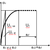
Uc tot is a function that is described by a parabolic func- tion having in a common case an exponent equal to n [6,14].
The function qf = f(lreq) is approximated as a linear one, using the following two given limiting conditions:
pre-stressed two-layer beam with fibered HSC in its com- pressed zone was analyzed. The compression zone of the beam section is made of HSC 90, for which (according to Euro Code [14]) fcm = 98 MPa, n = 1.4, ec el ul = 0.00223 (see Table 2), ec2 = 0.0026, m = 0.2, fctm = 5 MPa, ect ul =
0.12 �� 10��3. For the given beam the SF volume ratio, qf,
was calculated for a required ductility parameter, lreq = 2lHSC.
According to Eq. (16), the minimum contribution of fibers to the plastic deformations is
 fcm
fcm
ecfmin ¼
ectul m
12 10��5

 ¼ 0:2
¼ 0:2
¼ 0:6 X 10��3
The beam section��s compression zone ductility parameter is obtained, using Eq. (10), as follows:
l ¼ U ctot ¼ fcmec2½n=ð1 þ nÞ] ¼ 980:0026½1:4=ð1 þ 1:4Þ] ¼ 1:36
HSC
U cel
0:5ecelulfcm
0:50:0022398
0 Sec
lHSC
M r
 ¼ 1:36 M 0 ¼ 1:361:2 ¼ 1:64
Fig. 3. HSC and fibers PED potentials, Uc tot and Uf (Ucel �C elastic concrete energy; Uc tot �C total energy; and Uf �C plastic energy due to SF addition).
Then, according to the given design data, the required duc- tility parameter equals to
6 I. Iskhakov, Y. Ribakov / Materials and Design xxx (2007) xxx�Cxxx
lreq ¼ 2lHSC ¼ 21:64 ¼ 3:28
The allowed maximum value of the required ductility, according to Eq. (20), is
l ¼ 2ec2 þ U ctot ¼ 22:6 þ 1:64 ¼ 3:97
of the pre-tensioned members�� transfer length. It allows more uniform distribution of the pre-stressing forces along the ends of the beams and increases the elements�� efficiency. In other words, SFHSC/NSC pre-stressed beams become high performance elements.
reqmax
ecelul
U cel
2:23
Design of pre-stressed two-layer steel fibered beams
lreqmax ¼ 3:97 > lreq ¼ 3:28 ! OK;
i.e. the calculated value of the ductility parameter is under the allowed maximum value.
A minimum value of the SF volume ratio (according to [12]):
 fctm 5

 f min 2:5 2:5
A minimum value of the required ductility according to Eq. (20)
l ¼ 2ecf min þ U ctot ¼ 20:6 þ 1:64 ¼ 2:18
forms a new class of problems for RC structures. It
includes a number of innovative sub-problems, like defini- tion of an HSC class, obtaining the lower and the upper limits of the SF volume ratio, calculation of the SF volume ratio as a function of required pre-stressed section ductility, etc. The authors have already defined the HSC [6].
In this study a method for calculation of lower limit of the HSC class for two-layer pre-stressed beams is pro- posed. Two-layer beams have HSC in the compressed zone, which has higher cracking bearing capacity in bending. Using HSC class, selected according to the proposed method, prevents a necessity for using pre-stressed tendons
reqmin
ecelul
U cel
2:23
in a section��s compressed zone, which decreases the section
A design value of the SF volume ratio according to Eq. (23)
cracking bending moment.
It is also shown that the ductility parameter for a two-
qf min
q ¼

ðl �� l Þ
layer section, consisting of compressed HSC and tensile
 lreqmin
2
�� lHSC
req
HSC
pre-stressed NSC zones, is very small and its value is near to 1.0, i.e. a bending element section is brittle. It limits the
 ¼ 2:18 �� 1:64 ð2:72 �� 1:64Þ¼ 4:0%
It should be mentioned that in most experimental studies the SF volume ratio, qf, was 2.5% or less.
The corresponding maximum value of qf may be found using Eq. (23) after substituting lreq max instead of lreq:
application possibilities of such structures under seismic and other dynamic loadings. Therefore it is an additional reason to use SF in order to get HPC in the section��s com- pressed zone. It should be also mentioned that because the concrete action in tension is neglected, there is no reason to use HPC in the section��s tensile zone and no fibers are
qf min
q ¼ ðl

�� l Þ
added to NSC. Hence any changes, providing required
f max
lreq min
2
�� lHSC
req max
HSC
ductility of the RC section, may be achieved by using
HPC in its compressed zone only.
 ¼ 2:18 �� 1:64 ð3:97 �� 1:64Þ ¼ 8:63%
The design value, qf = 4.0%, belongs to the interval be- tween qf min = 2% and qf max = 8.63%, satisfying the condi- tion qf min 6 qf 6 qf max.
7. Results and discussion
Two-layer beams with HSC in section��s compressed zone and NSC in the tensile one are effective as bending pre-stressed elements. As it is known, presence of pre- stressed tendons significantly increases the section��s ductil- ity, because the tendons�� high strength steel exhibits brittle behavior, i.e. it has no definite yielding point at the stress�C strain curve.
The HSC layer can be also steel fibered, which allows improving the beams compressed zone plastic properties. Moreover, addition of steel fibers significantly improves the bonding between the concrete matrix and the pre- stressed reinforcement. It provides common action of the concrete and steel tendons, which is very important for such type of structures.
Another important contribution of steel fibers to pre- stressed concrete structures�� behavior is essential reduction
The minimum SF volume ratio for different HSC classes
was found based on [12]. It shows that the ratios of 0.5, ... , 2.5%, used by many researchers in experimental works, are close only to the minimum SF volume ratio. These ratios correspond to concrete transverse (Poisson��s) tensile strains, but they do not always ensure the section��s required ductility. A real value of an SF volume ratio is a function of the required ductility, which, in turn, is a design parameter. Besides, the maximum additional plastic defor- mations in beams, contributed by fibers, cannot exceed those in beams without fibers. Based on these require- ments, a linear approximation of the ����SF volume ratio �C required ductility���� function is proposed. It allows calcula- tion of SF volume ratio for a required section��s ductility.
8. Conclusions
A design method for two-layer bending pre-stressed beams, consisting of steel fibered high strength concrete in compressed zone and normal strength concrete in tensile one is proposed. It was shown that calculation of fibers�� volume ratio is important for design of two-layer bending elements, like that of reinforcing steel bars for usual RC ones. It was demonstrated that in this case two-layer
I. Iskhakov, Y. Ribakov / Materials and Design xxx (2007) xxx�Cxxx 7
SFHSC/NSC elements become high performance concrete ones.
A strategy for definition of the HSC class lower limit, used in the compressed zone of a two-layer pre-stressed beam with a given NSC class, is proposed. It was demon- strated that steel fibers have little effect on beams elastic deflections, but increase the ultimate deflections, due to the SF plastic energy dissipation potential.
NSC, used in the section tensile zone, contributes addi- tionally about 20% to the section��s plastic energy dissipa- tion, compared to one-layer HSC beams.
Based on the fact that the fibers take the tensile stresses, yielding cracks in the concrete matrix, a design method for calculation of the SF volume ratio, as a function of required ductility, was proposed. A numerical example, illustrating the efficiency of this method, showed that the SF volume ratios, used in experimental works previously carried out by other researchers correspond only to the fibers�� lower limit requirements.
A theoretical background for quantitative definition of two-layer beams SF volume ratio, presented in this paper, allows obtaining the required sections ductility parameter and forms a basis for a new design technique. It also pro- motes further experimental investigations of HPC structures.
References
[1] Magnuson J, Hallgern M. Reinforced high strength concrete beams subjected to air blast loading. In: Jones N, Brebbia CA, editors. Structures under shock and impact, 8th ed., vol. VIII. WIT Press; 2004.
[2] Chekanovich M. New structural concepts for utilization of high strength concrete and steel. In: Konig G, Dehn F, Faust T. High strength/high performance concrete, vol. 1. Leipzig; June 2002. p. 103�C11.
[3] Lin CH, Lee FS. Ductility of high performance concrete beams with high strength lateral reinforcement. ACI Struct J 2001;98(4):600�C8.
[4] Shah SA, Ribakov Y. Experimental and analytical study of flat-plate floor confinement. Mater Des 2005;26(8):655�C9.
[5] Hoff GC. HPC/HSC �C a North American perspective: In: Konig G, Dehn F, Faust T. High strength/high performance concrete, vol. 1. Leipzig; June 2002. p. 63�C76.
[6] Iskhakov I, Ribakov Y. A design method for two-layer beams consisting of normal and fibered high strength concrete. Mater Des 2007;28:1672�C7.
[7] Savir Z, Dancygier AN. Structural behavior of high strength reinforced concrete with steel fibers. In: Zingoni A, editor. Progress in structural engineering, mechanics and computation. London: Tailor and Francis Group; 2004.
[8] Narayanan R, Darwish YIS. Use of steel fibers as shear reinforce- ment. ACI Struct J 1987(May�CJune):216�C26.
[9] Padmarajaiah SK, Ramaswamy A. Behavior of fiber-reinforced pre- stressed and reinforced high-strength concrete beams subjected to shear. ACI Struct J 2001;98(5):752�C60.
[10] Iskhakov I. Influence of concrete pre-stressing and gravitation loading on plastic energy dissipation and ductility of RC elements in seismic zones. In: Jones N, Brebbia CA, editors. Structures under shock and impact, 8th ed., vol. VIII. WIT Press; 2004. p. 241�C51.
[11] Xue W, Li L, Cheng B, Li J. The reversed cyclic load tests of usual and pre-stressed concrete beams. Eng Struct 2007. Available from: http://www.sciencedirect.com.
[12] Petitjean J, Resplendino J. French recommendations for ultra-high performance fiber-reinforced concrete. In: Konig G, Dehn F, Faust T. High strength/high performance concrete, vol. 1. Leipzig; June 2002. p. 485�C98.
[13] Gorshenina EB. State and crack formation of bending RC members at contrary moment action. In: Proceedings of the 2 Russian (International) conference on concrete and reinforced concrete, Moscow; September 2005. p. 368�C73.
[14] Euro Code 2: Design of concrete structures �C part 1-1: General rules for buildings; December 2004.
[15] Iskhakov I. Quasi-isotropic ideally elastic-plastic model for calcula- tion of RC elements without empirical coefficients. In: Zingoni A, editor. Structural engineering mechanics and computation, vol. 1. Elsevier; 2001. p. 367�C74.
[16] Dovric DJ. Earthquake resistant design for engineers and architects. John Wiley and Sons; 1995.
[17] Dumet TB, Pinheiro LM. Experimental investigation of the local bond stress-slip behavior of pre-tensioned strands embedded in plane and steel-fibered reinforced concrete. In: Konig G, Dehn F, Faust T. High strength/high performance concrete, vol. 1. Leipzig; June 2002. p. 221�C34.
[18] Lapko A, Sadowska-Buraczewska B. Carrying capacity and defor- mability of hybrid beams made of HSC and normal concrete. In: Konig G, Dehn F, Faust T. High strength/high performance concrete, vol. 1. Leipzig; June 2002, p. 137�C48.
,
Two-layer pre-stressed beams consisting of normal and steel fibered high strength concrete
I. Iskhakov, Y. Ribakov *
Department of Civil Engineering, Ariel University Center of Samaria, P.O. Box 3, Ariel 44837, Israel
Received 7 April 2007; accepted 10 April 2007
Abstract
The paper is focused on analysis of two-layer bending pre-stressed beams consisting of steel fibered (SF) high strength concrete (HSC) in compressed zone and normal strength concrete (NSC) in tensile zone. Investigation of such beams is important for RC structural design, because calculation of fibers volume ratio is significant, like that of reinforcing steel bars for usual RC elements. In other words, such elements are made of high performance concrete (HPC). There is a growing tendency that more effective HPC structures replace NSC ones, first of all in pre-stressed elements. Definition of the HSC class lower limit, to be used in the compressed zone of a two-layer pre-stressed beam, is given. It was demonstrated that SF have little effect on the beam elastic deflections. However, the ultimate deflec- tions of the section increase because additional potential for plastic energy dissipation (PED) in the bending element. NSC, used in the section tensile zone, contributes additionally about 20% to the section��s PED potential compared to one-layer HSC beams. In order to guarantee sufficient section��s ductility of the pre-stressed beams, required to withstand dynamic loadings, a minimum SF ratio is pro- posed to be considered. The fibers take the tensile stresses, yielding cracks in the concrete matrix. A design method for calculation of the SF volume ratio, as a function of required ductility, is proposed. A numerical example, illustrating the efficiency of this method is presented.
© 2007 Elsevier Ltd. All rights reserved.
Keywords: Normal strength concrete; High strength concrete; Steel fibers; High performance concrete; Two-layer pre-stressed beams
1. Introduction
High strength concrete (HSC) was one of the interesting and challenging innovations in concrete structures in the last decades. This material became not only a topic for aca- demic investigations, but gradually has been applied in real structures. Now it is more common to speak about high performance concrete (HPC) instead of HSC. Many exper- imental investigations were aimed at studying the behavior of HSC or/and HPC structures [1�C4]. As it was mentioned at the International Symposium on Utilization of HSC/ HPC in 2002, there was no final agreement regarding the HSC definition [5]. A strong definition of HSC has been
* Corresponding author. Tel.: +9723 906 6327; fax: +9723 906 6351.
E-mail addresses: yizhak@ariel.ac.il (I. Iskhakov), ribakov@ariel.ac.il (Y. Ribakov).
given by the authors [6]. According to the definition, HSC was defined as concrete satisfying the following requirements: absence of a download branch in the concrete parabolic diagram; minimum exponent of the concrete ����stress�Cstrain���� function; and minimum ductility parameter of the concrete under compression. Additionally it was reported that HSC is characterized by a strength value, which corresponds to a transition from an elastic�C plastic stone material to a brittle one [6].
Following the definition given in [6], HSC should reach a compressive strength of fc P 70 MPa. However, the material exhibits pure brittle behavior. In order to be able to fully utilize the HSC strength capacity, taking additional structural measures is required to ensure the concrete matrix necessary ductility [3]. In order to improve the HSC behavior, i.e. to increase its ductility, steel fibers (SF) are usually added to the concrete matrix [7�C9].
0261-3069/$ - see front matter © 2007 Elsevier Ltd. All rights reserved. doi:10.1016/j.matdes.2007.04.013
2 I. Iskhakov, Y. Ribakov / Materials and Design xxx (2007) xxx�Cxxx
However, cracks appear in the concrete tensile zone, and for this reason its contribution to the bending elements car- rying capacity is neglected. Hence it is logically to use two- layer beams consisting of steel fibered HSC (SFHSC) in the section��s compressed zone and normal stress concrete (NSC) in the tensile one [6]. This approach decreases the SF expenditure, prevents brittle behavior of the section��s compressed zone and yields a more effective and economi- cal design solution.
It was shown that two-layer beams are effective as bend- ing pre-stressed elements [9,10], in which SF increase the HSC plasticity in a beam compressed zone. Additionally, using fibers significantly improves the bonding between the concrete matrix and the pre-stressed reinforcement [9,11,18]. Moreover, reducing of the pre-tensioned mem- bers transfer length is one of the SF major contributions to the effectiveness of the pre-stressed concrete elements [9]. It means that two-layer pre-stressed beams consisting of SFHSC and NSC (SFHSC/NSC) become HPC ele- ments. Using SF is also favorable for dissipation of energy at the large displacements stage, which is especially impor- tant from the beam��s bearing capacity viewpoint.
Design methods for two-layer SFHSC/NSC pre-stressed beams are still not enough developed. Furthermore, design of such beams forms new problems in reinforced concrete (RC) structures:
 obtaining the HSC class for a pre-stressed beam accord- ing to a given NSC one;
 calculation of steel fibers ratio as a function of the required pre-stressed section��s ductility;
 calculation of minimum and maximum SF volume ratios.
Usually, selection of the SF volume ratio was made based on engineering experience, technological require- ments, etc. Most experimental investigations have been curried out for SF volume ratios that were selected in this way and varied from 0.5% to 2.5% [1,7,9]. The lower limit of this ratio is recommended in [12].
Since HPC structures are more effective and replace the NSC ones, especially in pre-stressed elements, it is impor- tant to develop a strong theoretical background for design of such elements. This paper is focused on theoretical anal- ysis of the above mentioned problems from the two-layer SFHSC/NSC pre-stressed beams viewpoint. It is based on experimental investigations that have been performed by other researchers [1,3,7�C9,17,18]. Solving these problems has similar importance for modern structural design, as methods for calculation of reinforcing steel ratio for the usual RC structures.
2. Calculation of lower HSC class limit for two-layer pre- stressed beams
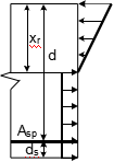
In tensile zone of bending RC elements, before cracking, appear plastic deformations in the concrete matrix, like in any tensile material [13]. A corresponding idealized ����stress�Cstrain���� diagram for tensile concrete is shown in Fig. 1a.
In this figure the symbols are given as in [14]:
fctm �C mean value of axial tensile strength of concrete; Mr �C section bottom (pre-stressed) zone cracking bend- ing moment;
xr�C corresponding neutral axis depth of the compressed zone;
M 0r �C section top zone cracking bending moment (with- out reinforcement);
x0r �C corresponding neutral axis depth of the compressed zone;
Asp �C pre-stressed tendons cross sectional area.
The section bottom zone cracking moment (see Fig. 1b)
M r ¼ 0:167bh2fctm½ð1 �� xrÞðxr þ 3Þþ 2nqð2:73 �� xrÞ] ð1Þ
where xr = xr/h, n = Es/Ec and q = As/(bd).
For example, for a given beam rectangular section with the following data: b = 30 cm, h = 60 cm, ds = 0.1d, d =
0 4 8 12
Mr 
ect10 5
fctm
M'r 
sc
Fig. 1. Behavior of pre-stressed RC bending element before cracking: (a) an idealized ����stress�Cstrain���� diagram of tensile concrete; (b) crack limit state under external moment; and (c) crack limit state due to pre-stressing forces.
I. Iskhakov, Y. Ribakov / Materials and Design xxx (2007) xxx�Cxxx 3
0.91 h, n = 9, q = 1%, f
= 1.77 MPa, the section lower
�� �� ec \nl
ctm
zone bending moment at cracking Mr = 62.33 kN m.
For the section upper zone (without reinforcement) the
rc ¼ fcm 1 �� 1 ��
ec2
ð7Þ
 bending moment at cracking for a given x0r x0r=h 0:5 can be obtained as follows:
 M 0 ¼ 0:167bh2fctmð1 þ 4nqÞ¼ 43:2 kN m;
M r ¼ 1:443M 0r ð2Þ
Experimentally, the relation between M 0r and Mr was investigated by many researches [11,13], etc. As it can be followed from [11], for three pre-stressed beams that were

where n is the exponent according to Table 3.1 [14] and ec2
is the strain at the maximum strength.
As it was demonstrated in the previous work, carried out by the authors [6], for HSC class 70 and higher
n ¼ 1:4 ¼ const; ec2 ¼ 0:0026 ¼ const ð8Þ
The total energy dissipation potential of the section��s compressed zone is
Z ec2


oretically obtained result (see Eq. (2)).
Z ec2 ��

�� eHSC\nl
If a pre-stressed element��s section has two-layers, the minimum concrete tensile strength for the upper HSC layer
fcm
0
1 �� 1 ��
n

ec2
deHSC
is
min f HSC ¼ M r f NSC
ð3Þ
¼ fcmec2 1 þ n ð9Þ
For example, for HSC class 90, according to Eq. (6),
ctm
M 0r
ctm
U cel ¼ 0:5ecelulfcm ¼ 0:52:23 X 10��3
fcm ¼ 1:115 X 10��3
fcm
In this case cracks will not appear in that layer under neg- ative moment due to pre-stressing forces. This condition may be used to calculate the HSC class according to a gi-
According to Eqs. (9) and (8),
U ¼ 2:60 X 10��3 1:4 f ¼ 1:36 X 10��3f


ven bottom layer NSC class. This condition also eliminates
ctot
1 þ 1:4
the necessity for using additional pre-stressing reinforce- ment in the upper (compressed) section��s zone. At the same
The ductility parameter is
U ctot
time Eq. (3) defines a lower value of the HSC class that
may be used in two-layer beams for a given NSC class.
lHSC ¼ U
cel
¼ 1:22 ð10Þ
The real HSC class should be selected based on the design value of the compressed concrete strength.
3. Ductility of a pre-stressed concrete section without fibers
Table 3.1 from [14] defines strength and deformation characteristics for concrete classes 16, .. ., 90. The secant modulus of elasticity, Ecm, for each class is given for rc = 0 ... 0.4 fcm, where fcm is the mean value of concrete compressive strength. The table does not contain concrete limit elastic deformations, ec el ul, that are required for cal- culations of the section��s ductility.
It is possible to calculate the above mentioned deforma- tions as follows:
fcm
i.e. the result is close to 1.0, as in the case of an elastic material.
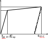
It is suggested that pre-stressed steel reinforcement in the tensile zone is deformed according to be-linear diagram with hardening (Fig. 2). The coordinates of the intersection point between the two branches of the diagram are fpk01 and (fpk01/Esp); the final point coordinates are fpk and esp ul, but the ultimate deformation, esp ul, is unknown. Here, fpk is characteristic tensile strength of pre-stressing steel; fpk01 is characteristic 0.1% proof-stress of pre-stressing steel; Esp is a design value of modulus of elasticity of pre-stress- ing steel; and esp ul is the strain of pre-stressing steel at max- imum load.
Following [10], the elastic and plastic potentials of the pre-stressing high strength steel (HSS) are
 ecelul
cm
ð4Þ
According to this equation, the concrete limit elastic defor- mations for the above mentioned concrete classes are (see Table 2)
ecelul ¼ ð0:83; ... ; 2:23ÞX 10��3 ð5Þ
The elastic energy potential of an HSC section compressed zone is
U cel ¼ 0:5ecelulfcm ð6Þ
In order to calculate the section��s compressed zone total energy dissipation, a concrete stress�Cstrain relationship
ssp
 fpk
fpk
pk 01
0
esp
should be used. According to Euro code [14],
Fig. 2. The stress�Cstrain diagram of pre-stressed tensile steel.
4 I. Iskhakov, Y. Ribakov / Materials and Design xxx (2007) xxx�Cxxx
f 2
U spel ¼ E
"g2 �� 0:5gp
Esp
 þ 2f
þ 2f
espul
ð1 �� gpÞ#
ð11Þ
Table 2
 Values of ecelul
and minimum steel fibers volume ratio, qf, vs. f
ck/fcm

 sp pk
sp pk
f /f
40/48 45/53 50/58 55/63 60/68 70/78 80/88 90/98
and
U sppl
¼ ��e
spul
fpk01
�� Esp
fpk01
ð12Þ

103ecel ul 1.37 1.47 1.57 1.66 1.74 1.90 2.10 2.23
qf (%) 1.40 1.52 1.64 1.68 1.76 1.84 1.92 2.00
and NSC classes (see Table 1). Thus, we deal with an eco-
 where gp = fpk01/fpk.
A corresponding ductility parameter is
 U sppl
sp U spel
ð13Þ
nomical and improved (from the structural viewpoint) SFHSC/NSC pre-stressed beam.
Some conclusions may be done from the table:
•  SF do not affect the beam elastic deflections;
If the pre-stressed beam reinforcement stress rsp 6 fpk01, then the section��s tensile zone contributes little to its plastic energy dissipation, and in this case lsp = 1. However, if rsp > fpk01, then lsp = f (esp ul) > 1, and in this case the un- known ultimate steel deformation, esp ul, should be calcu- lated. It follows that for this reason an additional equation is required. For a bending element either the plain section hypothesis or section energy equation can be used [10].
4. Definition of the minimum SF volume ratio
There are two factors leading decrease in plastic energy dissipations (PED) of the two-layer pre-stressed bending section:
• HSC in its compressed zone;
•  HSS in its tensile zone.
SF increase the ultimate deflections of the section approximately twice, yielding additional PED potential of a bending element;
 NSC in the tensile layer of a section, in addition, con- tributes approximately 20% of the section PED potential compared to one-layer HSC elements.
Based on these conditions, it is possible to calculate the SF content quantitatively as a function of the required sec- tion��s ductility.
Fibered concretes take the transverse (Poisson��s) tensile stresses, acting in the section, and in this case the SF role is to replace the conventional reinforcing steel. In order to provide sufficient ductility, a minimum fiber content, which guarantees that fibers will take the tensile stresses, if con- crete matrix cracks, is considered [12]. According to this approach, the minimum fiber volume ratio, min qf, is defined as follows:
It is clear that energy dissipation should be provided, i.e.
1 W allow
 min qf ¼ W
rðW ÞdW P fctm % ð14Þ
HPC should be used. However, it is reasonably to use
HPC in the compressed zone only, because the concrete action in the tensile zone is neglected. Generally, in order to improve the section��s PED, SF are added. But, again, there is no sense to add SF for the whole section, because, on one hand, as it was mentioned above, the concrete action in tension is neglected, and on the other hand, SF do not affect the pre-stressing reinforcement at all. There- fore it is enough to use SF just in the concrete compressed zone. Moreover, presence of NSC just in the tensile zone increases the overall section ductility, and its influence is increased with increase in the difference between HSC
Table 1
Middle-span SFHSC/NSC beam deflections from four-point static tests in the elastic and ultimate stages (following [1])

ȫ�ױ�ҵ��������ֳɳ�Ʒ��������ѯ�źţ�biyezuopinvvp QQ��1015083682
������ҳ
��ת����ע����Դ��www.biyezuopin.vip


 sc fctm