.2009.02.207, available online at www.cjmenet.com; www.cjmenet.com.cn
Temperature Control System with Multi-closed Loops
for Lithography Projection Lens
NIE Hongfei1, LI Xiaoping1, *, and HE Yan2
1 State Key Laboratory of Digital Manufacturing Equipment & Technology, Huazhong University of Science and Technology, Wuhan 430074, China
2 Tianhua College, Shanghai Normal University, Shanghai 201815, China
Abstract: Image quality is one of the most important specifications of optical lithography tool and is affected notably by temperature, vibration, and contamination of projection lens(PL). Traditional method of local temperature control is easier to introduce vibration and contamination, so temperature control system with multi-closed loops is developed to control the temperature inside the PL, and to isolate the influence of vibration and contamination. A new remote indirect-temperature-control(RITC) method is proposed in which cooling water is circulated to perform indirect-temperature-control of the PL. Heater and cooler embedded temperature control unit(TCU) is used to condition the temperature of the cooling water, and the TCU must be kept away from the PL so that the influence of vibration and contamination can be avoided. A new multi-closed loops control structure incorporating an internal cascade control structure(CCS) and an external parallel cascade control structure(PCCS) is designed to prevent large inertia, multi-delay, and multi-disturbance of the RITC system. A nonlinear proportional-integral(PI) algorithm is applied to further enhance the convergence rate and precision of the control process. Contrast experiments of different control loops and algorithms were implemented to verify the impact on the control performance. It is shown that the temperature control system with multi-closed loops reaches a precision specification at ±0.006 ℃ with fast convergence rate, strong robustness, and self-adaptability. This method has been successfully used in an optical lithography tool which produces a pattern of 100 nm critical dimension(CD), and its performances are satisfactory.
Key words: projection lens, remote indirect-temperature-control, cascade control structure, parallel cascade control structure, nonlinear
proportional-integral(PI) algorithm
1 Introduction∗
As integrated circuits shrink, smaller critical dimension (CD) is demanded to make the control of the manufacture process more and more strict. Advanced optical lithography tool, as the most important equipment of the manufacture process, requires a more strict control over its micro-environment[1], such as temperature, cleanliness, air pressure, and humidity, etc. Temperature fluctuation in particular causes image distortion and image plane shift, and thus becomes one of the critical factors affecting the image quality of optical lithography tool. The temperature precision inside the projection lens(PL) is required to be close to 0.01 ℃ for a lithogrpahy tool to produce a pattern of less than 100 nm. Also a fast convergence rate of the temperature inside the PL is needed to decrease the cost of the ownership(CoO) of lithography. However, there is a big
|
* Corresponding author. E-mail: xpli@public.wh.hb.cn
This project is supported by National Hi-tech Research and Development Program of China(863 Program, Grant No. 2002AA4Z300), and National Basic Research Program of China (973 Program, Grant No.
2009CB724205)
|
challenge to achieve these goals, because the heater and cooler controlling the temperature are required to be operated away from the PL[2], otherwise its performance will be destablized by their vibration and contamination. Another reason is that PL has a complex internal architecture containing dozens of lens which causes several hours of inertia, so the temperature inside the PL responds rather slow and it takes a long time to adjust. Therefore, a new structure and algorithm become necessary and significant in the controlling of the temperature inside the PL.
Many temperature control structures have been presented. One of the well-known classical approaches is the single closed-loop control structure widely used in simple or lower precision temperature control systems[3]. When controlled object becomes more complex or produces distributed disturbances, cascade control structure(CCS) is proposed to improve precision and convergence rate[4,5]. Feedforward predictive control structure has been proved to have better performance to delay systems[6]. Another effective approach, parallel cascade control structure (PCCS), is also developed for the delay systems with distributed disturbances[7]. But using methods mentioned above[8], it is difficult to achieve high precision and fast convergence rate of the temperature inside the PL.
In this paper, a new approach, namely the multi-closed- loop temperature control system incorporating an internal CCS and an external PCCS is presented. The paper is roughly divided into four sections. The first section explains why a remote indirect-temperature-control method is applied. In the second part a multi-closed-loop temperature control structure is analyzed. In the third part,a dual-input dual-output nonlinear proportional-integral(PI) algorithm is set up to improve the convergence rate and precision of control process. In the last section of the paper, contrast experiments validating the effectiveness of such a system is shown, and finally, the conclusion is given.
2 Remote Indirect-temperature-control Method
To prevent vibration and contamination affecting perfor- mance of PL, a remote indirect-temperature-control method is proposed to control the temperature inside the PL. Unlike traditional method of direct heating and cooling control object, it stablizes temperature inside PL via heat exchange between cooling water and a cooling-jacket around the PL. Cooling water is transported through long-distance pipeline from TCU to the cooling-jacket. TCU consists of water tank, temperature sensor, temperature controller, heater, cooler, and pump. It is used to condition the temperature of the cooling water to a desired value. TCU and lithography tool are placed in different clean rooms, as shown in Fig. 1. Theoretically, this method belongs to the open-loop structure.
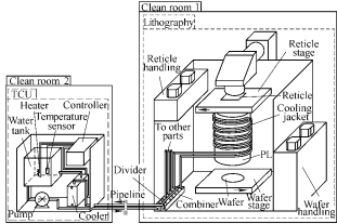
Fig. 1. Remote indirect-temperature-control system of PL
Besides PL, other parts of lithography, such as wafer stage, reticle stage, reticle handing, wafer handing, and so on, also generate heat during their operation. Cooling water from TCU is additionally used to cool other parts of lithography. A circulation system is necessary to recycle the cooling water to save maximum energy. Fig. 1 shows the circulation system which consists of TCU, divider, combiner, cooling-jacket, and pipelines. Cooling water flows out from the tank is pumped to the cooling-jacket through pipelines and divider, and finally flows back to the tank through combiner, pipelines, and cooler.
Analysis on circulation system of the cooling water tells three main factors affecting the temperature inside the PL: multi-disturbance, multi-delay, and large inertia. Multi-disturbance includes temperature fluctuation of the cooling water, internal heat dissipation of the PL, and heat exchange between PL and external mediums. The temperature fluctuation of cooling water is caused by several factors, including self-excited temperature oscillation caused by nonlinear heating and cooling inside the TCU, conductive heat tranfer between pipelines, ambient gases, and heat generation of other parts of lithography tool. Temperature fluctuation of cooling water reachs 0.1 ℃ under the worst circumstances in this circulation system. Internal heat dissipation of PL is due to two factors, one is the internal radiation and conductive heat tranfer when laser goes through the lens, another is the conductive and convective heat tranfer between the lens and internal purified nitrogen. As for the laser, its heat dissipation is roughly 15 W. The heat exchange between PL and external mediums is resulted from two ways, one is the mutual heat exchange between PL and its neighboring components, another is the conductive and convective heat tranfer between outer wall of PL and ambient gases. However, the heat exchange between PL and external mediums is difficult to calculate due to its complexity. Multi-delay mainly includes 10 s delays of heating and cooling in TCU, 3 min delay of the cooling water transport, and 10 min delays of heat exchange between water jacket and PL. In addition, complex structure of the PL leads to uneven heat exchange, and the inertia due to its large volume results in slower temperature variation compared with the objects in smaller volume.
The above analysis indicates that it is very difficult to realize high precision and fast convergence rate of temperature inside the PL via open-loop structure merely. There is also large steady-state error in the open-loop structure. In the following sections, we will introduce an improved control structure for the temperature control inside the PL and explain how to increase the precision and the convergence rate of temperature control.
3 Multi-closed Loop Control Structure
The multi-closed-loop temperature control structure is composed of an internal CCS and an external PCCS.
3.1 Cascade control structure
|

Fig. 2. Block diagram of the CCS
|
The internal CCS of the PL temperature control is shown in Fig. 2. There are two feedback loops with two controllers respectively. The main loop attributes to the temperature (Tl) inside the PL. The temperature (Tw) of the cooling water inside the TCU tank forms the secondary loop. It is easy to analyze the operation of this system qualitatively. If the temperature inside the PL deviates the desired value (Ts), the control algorithm embedded in the main controller will compute a new temperature setpoint value (Tt) of cooling water by comparing the deviation between measured temperature Tl and the desired value Ts. Then the new setpoint value Tt is send to the temperature controller of the TCU. Subsequently according to the deviation between measured temperature Tw and new setpoint value Tt, control algorithm in the TCU calculates the input of heater and cooler and warms up or cools down the cooling water in the TCU tank to the new setpoint value. The desired setpoint value of the temperature inside the PL is given by a machine constant. The Tl control loop is a slow control loop. The Tw control loop is a fast control loop and can quickly follow the main loop setpoint value Tt. When a new setpiont Tt is sent to the TCU, it takes a few minutes to adjust water temperature in the TCU tank to the new setpoint value. The secondary loop has a strong inhibition capacity for its internal disturbance. In addition, it can also decrease the effect of nonlinearity and delay for the main loop.
|

Fig. 3. Control schematic diagram of the cascade control system
|
Fig. 3 shows the control schematic diagram of the cascade control system mentioned above in details. In the following diagrams and equations, Gt(s) represents the transfer function of the heater and the cooler, Gp(s) represents the transfer function of the pipeline, and Gl(s) represents the transfer function of the PL. Gm(s) represents the transfer function of the main controller and Gs(s) represents the transfer function of the secondary controller. Hm(s) represents the transfer function of the main loop measuring device and Hs(s) represents the transfer function of the secondary loop measuring device. τt represents the delay of the cooling water in the TCU tank, τp represents the delay of cooling water through the pipeline, and τl represents the delay of the heat exchange inside the PL. Nt(s) represents the external disturbance of the TCU, Np(s) represents the external disturbance of the pipeline, Ne(s) represents the external disturbance of the PL, and Nn(s) represents the internal disturbance of the PL. Rl(s) represents the input temperature inside the PL and Rt(s) represents the input temperature of the cooling water in the TCU tank. Cl(s) represents the output temperature inside the PL and Ct(s) represents the output temperature of the cooling water in the TCU tank.
The transfer function of input and output in the
secondary loop can be expressed as
C st ( ) =  R s G s G st ( ) s ( ) t ( )exp(−τts)+N st ( ) . (1)
1+Hs ( )s G s G ss ( ) t ( )exp(−τts)
Under the steady state of the secondary loop, the output Ct(s) is equivalent to the input Rt(s) approximately. So the transfer function of input and output in main loop can be simplified as
C sl ( ) =  G sb ( ) , (2)
1+H m ( )s G s G s G sm ( ) p ( ) l ( )exp(− +(τ τp l ) )s
where
G sb ( ) [= R s G sl ( ) m ( )+N s G s G sp ( )] p ( ) l ( )exp( (−τ τp + l ) )s +
N s G se ( ) l ( )exp(−τls) +N sn ( ) . (3)
Earlier studies show that the time constant of the PL is about 4 h[9]. The transfer function of Gl(s) is identified as
|
G sl ( ) =  0.005 7 . 0.005 7 .
s+ 0.005 9
The transfer function of Gp(s) is identified as
|
(4)
|
|
0.074s+ 1.307 10× −5
 G sp ( ) = − . G sp ( ) = − .
|
(5)
|
s 2 + 0.104s+1.35 10× 5
For the simple closed-loop CCS, it is easy to eliminate the steady-state error. However, according to Eqs. (2) and (3), convergence rate of the temperature inside the PL is slow from start to steady state because of the delay terms τp and τl. Meanwhile, it is difficult to achieve high precision of the temperature inside the PL because of the disturbance terms Np(s), Ne(s), and Nn(s). Under the condition of steady state, when the instantaneous temperature fluctuation of the cooling water is over 0.1℃ as a result of the Np(s) and Ne(s), the temperature fluctuation inside the PL is over 0.01 ℃. Several control periods is necessary to reach the next steady state. So PCCS is introduced to improve the control performance.
3.2 Parallel cascade control structure
|
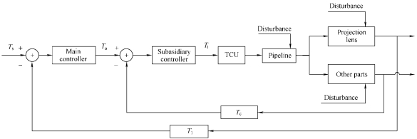
Fig. 4. Block diagram of the PCCS
|
The external PCCS is shown in Fig. 4. This figure hides the control loop Tw and identifies the major components in the system as blocks. Compared with the CCS, there are also two control loops with two controllers respectively, one is the main loop for the temperature (Tl) inside the PL, and the other is the subsidiary loop for the temperature (Tc) of cooling water at the combiner. The difference is that the main control object and the subsidiary control object are parallel, and the output of subsidiary object is not the input of main object. In this system, the control algorithm embedded in the main controller determines a new optimal temperature (To) setpoint value of the cooling water at the combiner according to the deviation between Tl and Ts. Then the control algorithm in the subsidiary controller calculates the input of TCU according to the deviation between Tc and To. The Tl control loop is a slow control loop. The Tc control loop is a fast control loop, which is used to follow and predict the optimal temperature setpoint value of the cooling water at the combiner quickly. When the temperature inside the PL is at the desired value, the temperature of the cooling water at the combiner is the optimal temperature. This optimal temperature will be saved and kept as a constant. From the view of disturbance inhibition, the subsidiary loop is operated according to the similar principle of feed-forward control and plays an indirect feed-forward control role. The difference is that the disturbance must be measurable for feed-forward control structure, while the PCCS can be applied to the un-measurable disturbance. Another advantage of the PCCS is that it can accelerate the convergence rate of the main loop.
|

Fig. 5. Control schematic diagram of the parallel cascade control system
|
Fig. 5 shows the control schematic diagram of parallel cascade control system mentioned above in details. In the following diagrams and equations, Gc(s) represents the transfer function of the cooling water at the combiner and Gd(s) represents the transfer function of the subsidiary controller. Hd(s) represents the transfer function of subsidiary loop measuring device. Rc(s) represents the input temperature of the cooling water at the combiner. Cc(s) represents the output temperature of the cooling water at the combiner.
The transfer function of input and output in the subsidiary loop is given by
{[R s G sc( ) d( )+N s G sp( )] p( )exp(−τps)+N s G se( )} c( )
C sc( ) =  .
.
1+H s G s G s G sd( ) d( ) p( ) c( )exp(−τps)
(6)
Under the steady state of the subsidiary loop, the output Cc(s) is equivalent to the input Rc(s) approximately. So the transfer function of input and output in main loop can be reduced to
C sl ( ) = R s G s G sl ( ) m ( ) l ( )exp(−τls)+N s G sn ( ) c ( ) . (7)

G sc ( ) +H s G s G sm ( ) m ( ) l ( )exp( −τls)
Comparing Eqs. (2), (3), and (7), we can see that the disturbance terms Np(s), Ne(s), and the delay term of τp are isolated from the main loop, and only the disturbance term Nl(s) and the delay term τl remain in the main loop. So the introduction of the subsidiary loop achieves the separation of the multi-delay and multi-disturbance in physical structure and isolates the influence of the nonlinear, multi-delay, and multi-disturbance for the main control object. This structure also reduces the difficulty of the controller design. Even if there are some temperature fluctuations of the cooling water, it can also be compensated by the subsidiary controller. As a result, the temperature inside the PL can be controlled with high precision and fast convergence rate.
4 Nonlinear Proportional-integral Algorithm
To further improve the system convergence rate and precision, a dual-input and dual-output intelligent controller embedded with nonlinear PI algorithm is designed, as shown in Fig. 6. The temperature deviation e1 inside the PL and the temperature deviation e2 of the cooling water at the combiner are the inputs of the controller. The outputs of the controller are the temperature setpoint value Tt of the cooling water inside the TCU tank and the temperature setpoint value To of the optimal cooling water at the combiner.
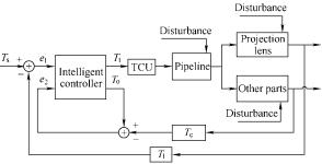
Fig. 6. Block diagram of PCCS with intelligent controller
The intelligent algorithm is embedded in the controller. It includes two hierarchies and is divided into five phases for the control process according to the ideal dynamic response curve. The upper hierarchy of the algorithm which determines the switch and choice between the five phases has been investigated in our previous work[10]. The
nonlinear PI algorithm utilized in the lower hierarchy will be discussed in the following paragraphs.
Considering the multi-disturbance characteristic of the temperature control system, the PI algorithm is preferred instead of the proportional-integral-differential(PID) algorithm, because the differential item will trigger high-frequency oscillations and increase steady-state error.
Fig. 7 shows the control schematic diagram of the nonlinear PI algorithm, in the following diagrams and equations, u1 represents the temperature setpoint value of the cooling water inside the TCU tank, u2 represents the temperature setpoint value of the optimal cooling water at the combiner, A11 represents the PI control law of e1 contribution to u1, A12 represents the PI control law of e1 contribution to u2, A21 represents the PI control law of e2 contribution to u2, and A22 represents the PI control law of e2 contribution to u2. W11, W12, W21, and W22 represent the data fusion coefficients.
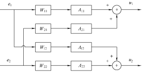
Fig. 7 Control schematic diagram of the nonlinear PI algorithm
The control algorithm can be expressed as
2
u ki ( ) =u ki ( − +1) ∑W ji∆A kji ( ) , (8)
j=1
where i=1,2, j=1,2, and ∆A is the basic discrete incremental PI control algorithm formulated as
∆A( )k = ∆K e kP ( )+K e kI ( ) , (9)
where ∆e(k)=e(k)–e(k–1), KP represents the proportio- nal coefficient, KI represents the integral coefficient, k represents sampling sequence, ui(k–1) and ui(k) represent the controller output at (k–1) and k moment respectively, e (k–1) and e(k) represent the deviation signal at (k–1) and k moment respectively.
The data fusion coefficients are computed by the producing rules. The detailed rules are presented as follows:
(1) if |e1|>a1, then W11=1, else W11=0;
(2) if |∆e1|>a2, then W12=1, else W12=0;
(3) if |e2|>a3, then W21=1, else W21=0;
(4) if | ∆ e2|>a4, then W22=1, else W22=0. Where a1 represents the deviation thresholds determined by the steady-state error of the temperature inside the PL, a2 represents the disturbance thresholds determined by transient error of the temperature inside the PL, a3 represents the deviation thresholds determined by the steady-state error of the cooling water temperature at the combiner, and a4 represents the disturbance thresholds determined by the transient error of the cooling water temperature at the combiner.
According to the producing rules and the input information of the control process, 16 kinds of different algorithms are obtained. The controller can choose any kind of algorithm according to the input data flexibly. This will not only improve the adaptability and convergence rate of the algorithm, but also enhance the robustness of the system and anti-disturbance capacity.
5 Experimental Verification of Control Structure and Algorithm
An experiment platform is built to validate the effectiveness of the approach presented in this paper as shown in Fig. 8, which include a dummy PL, temperature sensors, temperature measurement system, TCU, industrial computer, heat insulated room, light source, etc. The dummy PL has the same heat characteristic as the actual PL. The heat insulated room simulates the heat insulation function of lithography cover. The light source simulates the exposure light source using a 20 W incandescence light. Three temperature sensors which are high precision negative temperature coefficient thermistor with ±0.001 ℃ calibration accuracy are used to detect the temperature inside the PL, the cooling water temperature at the combiner, and the environmental temperature Ta outside the heat insulation room. The temperature measurement system consists of the Model 1590 Super-Thermometer and a multi-channel scanner with ±0.001 ℃ resolution. The TCU is configured with ±0.02 ℃ precision. The intelligent algorithm runs on the industrial computer.
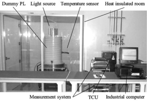
Fig. 8 Experiment platform of validation the control system
To examine the control structure and algorithm the following four experiments are carried out: (a) Using open-loop structure, (b) Using CCS with PI algorithm, (c) Using PCCS with PI algorithm, and (d) Using PCCS with nonlinear PI algorithm. In these experiments the desired value of PL temperature is 22 ℃, The parameters of the nonlinear PI algorithm are that a1 is 0.01℃, a2 is
0.005℃, a3 is 0.02 ℃, and a4 is 0.05 ℃.
Experiment results are shown in Fig. 9. In this figure, Fig. 9(a) displays the temperature curve of the open-loop structure. As is shown in fig. 9(a), the temperature Tl inside the PL is stabilized at 21.75 ℃ and unable to reach the desired value Ts when TCU is set to 22 ℃. As there exists the large steady-state error in the open-loop structure, using the closed-loop structure is necessary. Fig. 9(b) shows that it takes 20 hours to enter stable state using closed-loop CCS. Fig. 9(c) shows that the temperature is converged more rapidly than that in Fig. 9(b), but the precision of the temperature inside the PL can’t be further advanced. Temperature curve of the PCCS with nonlinear PI algorithm is shown in Fig. 9(d). It takes only 4.5 h to enter stability of 22±0.01 ℃ . Even if the environmental temperature Ta fluctuates within 22±2.5 ℃, the temperature inside the PL can still be stabilized within 22±0.006 ℃. It is clear that the new approach greatly improves the convergence rate, precision and anti-disturbance capacity of the system.
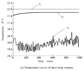
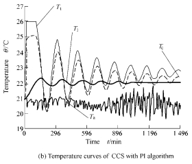
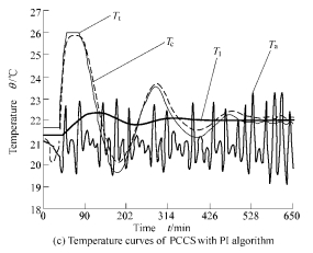
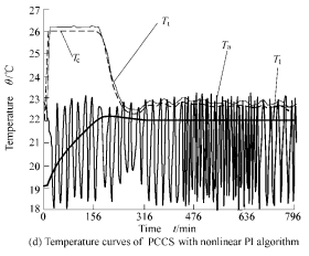
Fig. 9 Experimental results of different structure and algorithm
6 Conclusion
Temperature control precision can be improved in lithography PL by using multi-closed loop control system. Analysis and experiment reveal that PCCS with nonlinear PI algorithm has the capability of prediction and rolling optimization. It is better than open-loop structure and closed-loop CCS in convergence rate, control precision, and anti-disturbance capacity. It has been successfully used in optical lithography tool producing a pattern of 100nm. After simple improvement, it can also be used to control the temperature of other complex objects which need remote indirect-temperature-control, particularly the immersion fluid of the immersion lithography.
References
[1] SUGANAQA T, MAEJIMA S, HANAWA T, et al. Verification of optical proximity effect in immersion lithography[C]//Part of the SPIE conference on the International Society for Optical Engine- ering for optical Microlithography XIX, Flagello D G, SPIE, 2006, 6 154: 615–620.
[2] CHEN Weiming, HE Hao, LIU Yeyi. An algorithm for controlling objective lens temperature[C]//Part of the SPIE Conference on Metrology, inspection, and Process Control for Microlithography XIII, Bhanwar S, SPIE, 1999, 3 677: 377–381.
[3] WRIGHT D R, CLARK W D, HARTMAN D C, et al. Closed-loop temperature control system for a low-temperature etch chuck[C]// Part of the SPIE Conference on Advanced Techniques for Integrated Circuit Processing II, James A B, Gary C, Lloyd R H, et al, SPIE, 1993, 1 803: 321–329.
[4] EDUARDO C S, JESUS A. Decentralized cascade control of binary distillation columns[C]//Proceedings of the 2004 American Control Conference, Evanston I L, American Automatic Control Council, 2004, 4: 3 556–3 561.
[5] FANG Tiankong, YOU Pingchen, JING Mingxie, et al. Distributed temperature control system based on multi-sensor data fusion[C]// Proceedings of Fourth International Conference on Machine Learning and Cybernetics, Evanston I L, American Automatic Control Council, 2005, 1: 494–498.
[6] LING K V, WU Bingfang, HE Minghua, et al. A model predictive controller for multi-rate cascade systems[C]//Proceedings of Fourth International Conference on Machine Learning and Cybernetics, Evanston I L, American Automatic Control Council, 2004, 2: 1 575–1 579.
[7] SENINO D, BRAMBILLA A. An efficient structure for parallel cascade control[J]. Industrial and engineering chemistry research, 1996, 35(6): 1 845–1 852.
[8] CLARKE M E, XIA A, SMITH J, et al. Point-of-use ultra-pure water for immersion lithography[C]//The 17th Annual SEMI/IEEE on Advanced Semiconductor Manufacturing Conference, Boston, ASMC, 2006: 196–201.
[9] NIE Hongfei, LI Xiaoping. Modeling for lithography temperature control system based on gray identification[J]. Chinese Journal of Mechanical Engineering, 2008, 44(1): 98–101. (in Chinese)
[10] LI Xiaoping, NIE Hongfei, YU Bin. Non-linear PI-control temperature control algorithm for projection[C]//3rd International Symposium on Advanced Optical Manufacturing and Testing Technologies, HAN Sen, XING Tingwen, LI Yanqiu, et al, SPIE, 2007, 6724: 394–402.
Biographical notes
NIE Hongfei, born in 1978, is currently a doctor in School of Mechanical Science & Engineering, Huazhong University of Science and Technology, China. His research interests include high precision temperature control, advanced process control, etc.
Tel: +86-21-51315131-2067; E-mail: niehf2003@163.com
LI Xiaoping, born in 1966, is currently a professor in Huazhong University of Science and Technology, China. He received his MS degree from School of Mechanical Science & Engineering, Huazhong University of Science and Technology, China, in 1992. His main research interest is electromechanical control in optical lithography tool.
Tel: +86-21-51315131-2002; E-mail: xpli@public.wh.hb.cn
HE Yan, born in 1979, is currently a teacher in Tianhua College, Shanghai Normal University, China. She received her MS degree from College of Mechanical Engineering, Wuhan University of Technology, China, in 2004. Her main research interest is advanced process control.
Tel: +86-21-39966303; E-mail: hy_886@163.com


