Introductions to temperature control
and PID controllers
Process control system.
Automatic process control is concerned with maintaining process variables temperatures pressures flows compositions, and the like at some desired operation value. Processes are dynamic in nature. Changes are always occurring, and if actions are not
taken, the important process variables-those related to safety, product quality, and production rates-will not achieve design conditions.
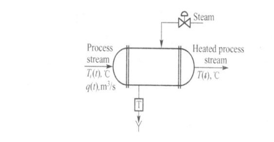
In order to fix ideas, let us consider a heat exchanger in which a process stream is heated by condensing steam. The process is sketched in Fig.1 
Fig. 1 Heat exchanger
The purpose of this unit is to heat the process fluid from some inlet temperature, Ti(t), up to a certain desired outlet temperature, T(t). As mentioned, the heating medium is condensing steam.
The energy gained by the process fluid is equal to the heat released by the steam, provided there are no heat losses to surroundings, that is, the heat exchanger and piping are well insulated.
In this process there are many variables that can change, causing the outlet temperature to deviate from its desired value. If this happens, some action must be taken to correct for this deviation. That is, the objective is to control the outlet process temperature to maintain its desired value.
One way to accomplish this objective is by first measuring the temperature T(t) , then comparing it to its desired value, and, based on this comparison, deciding what to do to correct for any deviation. The flow of steam can be used to correct for the deviation. This is, if the temperature is above its desired value, then the steam valve can be throttled back to cut the steam flow (energy) to the heat exchanger. If the temperature is below its desired value, then the steam valve could be opened some more to increase the steam flow (energy) to the exchanger. All of these can be done manually by the operator, and since the procedure is fairly straightforward, it should present no problem. However, since in most process plants there are hundreds of variables that must be maintained at some desired value, this correction procedure would required a tremendous number of operators. Consequently, we would like to accomplish this control automatically. That is, we want to have instuments that control the variables without intervention from the operator. This is what we mean by automatic process control.
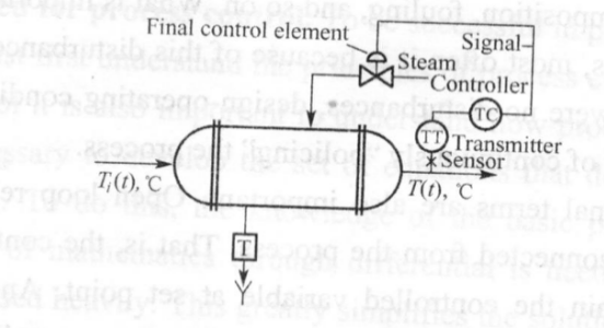
To accomplish this objective a control system must be designed and implemented. A possible control system and its basic components are shown in Fig.2.

Fig. 2 Heat exchanger control loop
The first thing to do is to measure the outlet temperature of the process stream. A sensor (thermocouple, thermistors, etc) does this. This sensor is connected physically to a transmitter, which takes the output from the sensor and converts it to a signal strong enough to be transmitter to a controller. The controller then receives the signal, which is related to the temperature, and compares it with desired value. Depending on this comparison, the controller decides what to do to maintain the temperature at its desired value. Base on this decision, the controller then sends another signal to final control element, which in turn manipulates the steam flow.
The preceding paragraph presents the four basic components of all control systems. They are
(1) sensor, also often called the primary element.
(2) transmitter, also called the secondary element.
(3) controller, the "brain" of the control system.
(4) final control system, often a control valve but not always. Other common final control elements are variable speed pumps, conveyors, and electric motors.
The importance of these components is that they perform the three basic operations that must be present in every control system. These operations are
(1) Measurement(M): Measuring the variable to be controlled is usually done by the combination of sensor and transmitter.
(2) Decision (D): Based on the measurement, the controller must then decide what to do to maintain the variable at its desired value.
(3) Action (A): As a result of the controller's decision, the system must then take an action. This is usually accomplished by the final control element.
As mentioned, these three operations, M, D, and A, must be present in every control system.
PID controllers can be stand-alone controllers (also called single loop controllers), controllers in PLCS, embedded controllers, or software in Visual Basic or C# computer programs.
PID controllers are process controllers with the following characteristics:
Continuous process control
Analog input (also known as "measurement" or "Process Variable" or "PV")
Analog output (referred to simply as "output")
Setpoint (SP)
Proportional (P), Integral (I), and/or Derivative (D) constants
Examples of "continuous process control" are temperature, pressure, flow, and level control. For example, controlling the heating of a tank. For simple control, you have two temperature limit sensors (one low and one high) and then switch the heater on when the low temperature limit sensor turns on and then turn the heater off when the temperature rises to the high temperature limit sensor. This is similar to most home air conditioning & heating thermostats.
In contrast, the PID controller would receive input as the actual temperature and control a valve that regulates the flow of gas to the heater. The PID controller automatically finds the correct (constant) flow of gas to the heater that keeps the temperature steady at the setpoint. Instead of the temperature bouncing back and forth between two points, the temperature is held steady. If the setpoint is lowered, then the PID controller automatically reduces the amount of gas flowing to the heater. If the setpoint is raised, then the PID controller automatically increases the amount of gas flowing to the heater. Likewise the PID controller would automatically for hot, sunny days (when it is hotter outside the heater) and for cold, cloudy days.
The analog input (measurement) is called the "process variable" or "PV". You want the PV to be a highly accurate indication of the process parameter you are trying to control. For example, if you want to maintain a temperature of + or - one degree then we typically strive for at least ten times that or one-tenth of a degree. If the analog input is a 12 bit analog input and the temperature range for the sensor is 0 to 400 degrees then our "theoretical" accuracy is calculated to be 400 degrees divided by 4,096 (12 bits) =0.09765625 degrees. We say "theoretical" because it would assume there was no noise and error in our temperature sensor, wiring, and analog converter. There are other assumptions such as linearity, etc. The point being--with 1/10 of a degree "theoretical" accuracy--even with the usual amount of noise and other problems-- one degree of accuracy should easily be attainable.
The analog output is often simply referred to as "output". Often this is given as 0~100 percent. In this heating example, it would mean the valve is totally closed (0%) or totally open (100%).
The setpoint (SP) is simply--what process value do you want. In this example--what temperature do you want the process at?
The PID controller's job is to maintain the output at a level so that there is no difference (error) between the process variable (PV) and the setpoint (SP).
In Fig. 3, the valve could be controlling the gas going to a heater, the chilling of a cooler, the pressure in a pipe, the flow through a pipe, the level in a tank, or any other process control system. What the PID controller is looking at is the difference (or "error") between the PV and the SP.
SETPOINT P,I,&D

 CONSTANTS

Difference error PID control

 algorithm
 process output
 variable
Fig .3 PIDcontrol
It looks at the absolute error and the rate of change of error. Absolute error means--is there a big difference in the PV and SP or a little difference? Rate of change of error means--is the difference between the PV or SP getting smaller or larger as time goes on.
When there is a "process upset", meaning, when the process variable or the setpoint quickly changes--the PID controller has to quickly change the output to get the process variable back equal to the setpoint. If you have a walk-in cooler with a PID controller and someone opens the door and walks in, the temperature (process variable) could rise very quickly. Therefore the PID controller has to increase the cooling (output) to compensate for this rise in temperature.
Once the PID controller has the process variable equal to the setpoint, a good PID controller will not vary the output. You want the output to be very steady (not changing) . If the valve (motor, or other control element) is constantly changing, instead of maintaining a constant value, this could cause more wear on the control element.
So there are these two contradictory goals. Fast response (fast change in output) when there is a "process upset", but slow response (steady output) when the PV is close to the setpoint.
Note that the output often goes past (over shoots) the steady-state output to get the process back to the setpoint. For example, a cooler may normally have its cooling valve open 34% to maintain zero degrees (after the cooler has been closed up and the temperature settled down). If someone opens the cooler, walks in, walks around to find something, then walks back out, and then closes the cooler door--the PID controller is freaking out because the temperature may have raised 20 degrees! So it may crank the cooling valve open to 50, 75, or even 100 percent--to hurry up and cool the cooler back down--before slowly closing the cooling valve back down to 34 percent.
Let's think about how to design a PID controller.
We focus on the difference (error) between the process variable (PV) and the setpoint (SP). There are three ways we can view the error.
The absolute error
This means how big is the difference between the PV and SP. If there is a small difference between the PV and the SP--then let's make a small change in the output. If there is a large difference in the PV and SP--then let's make a large change in the output. Absolute error is the "proportional" (P) component of the PID controller.
The sum of errors over time
Give us a minute and we will show why simply looking at the absolute error (proportional) only is a problem. The sum of errors over time is important and is called the "integral" (I) component of the PID controller. Every time we run the PID algorithm we add the latest error to the sum of errors. In other words Sum of Errors = Error 1 q- Error2 + Error3 + Error4 +…
The dead time
Dead time refers to the delay between making a change in the output and seeing the change reflected in the PV. The classical example is getting your oven at the right temperature. When you first turn on the heat, it takes a while for the oven to "heat up". This is the dead time. If you set an initial temperature, wait for the oven to reach the initial temperature, and then you determine that you set the wrong temperature--then it will take a while for the oven to reach the new temperature setpoint. This is also referred to as the "derivative" (D) component of the PID controller. This holds some future changes back because the changes in the output have been made but are not reflected in the process variable yet.


