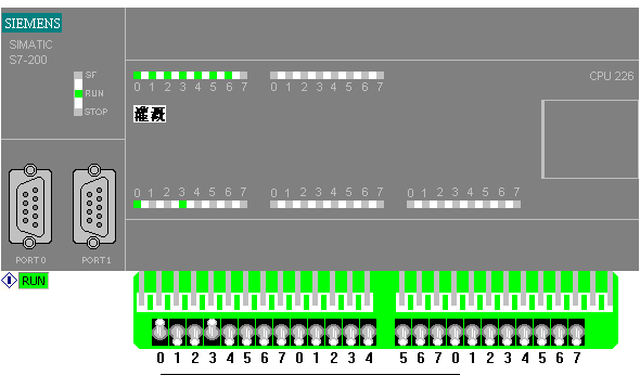
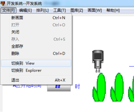
基于组态王+PLC的自动灌溉控制系统设计
摘 要
本设计使用西门子的S7-200 可编程序控制器(PLC)进行自动灌溉控制系统的设计。本系统共有三个灌溉区域进行控制,A区,B区,C区。每个区域采用不同的灌溉方式进行灌溉、A区,每次喷两分钟,暂停5分钟,循环十次后停止。B区采用旋转式喷头进行喷灌,工作5分钟,暂停20分钟,循环三次。C区,每两天喷灌一次,每次20分钟。系统通过设定各区灌溉开始和结束灌溉时间,跟读取的系统实时小时进行比较,控制自动启动各区进行灌溉。
同时系统通过检测实时的温度和湿度,检测下雨,作为控制前提条件。温度低禁止灌溉,湿度高禁止灌溉,下雨禁止灌溉。系统具有手动和自动操作模式,系统工作可靠,操作简单,能有效的对灌溉进行制。
通过分析控制要求,进行了总体设计,选择了硬件,进行了主电路和控制电路设计,设计了PLC的输入和输出接线图,编制了控制程序流程图,使用编程软件编写了梯形图和语句表程序,最后进行了调试,达到了预期的设计目的。
关键词:可编程控制器,自动灌溉,梯形图
Abstract
This design uses SIEMENS's S7-200 programmable controller (PLC) to design the automatic irrigation control system. The system has three irrigation areas for control, A area, B area and C area. Each area was irrigated and A area was irrigated for two minutes each time, suspended for 5 minutes, and after ten cycles. In the B area, the rotating sprinkler was used for sprinkler irrigation. The work was 5 minutes, 20 minutes were suspended and three cycles were circulated. Area C, sprinkled once every two days, 20 minutes each time. The system starts and ends the irrigation time in each area, and compares it with the real-time hours that the system reads, and controls the automatic start of irrigation in all areas.
At the same time, the system detects real temperature and humidity to detect rain as a precondition for control. Low temperature, no irrigation, high humidity, no irrigation, and no rain for rain. The system has the manual and automatic operation mode, the system works reliably, the operation is simple, and the irrigation can be made effectively.
Through the analysis of the control requirements, the overall design, selection of hardware, the main circuit and control circuit design, the design of PLC input and output wiring diagram, control program flowchart, using programming software compiled ladder diagram and instruction list program debugging, finally, to achieve the desired design purpose.
Key words: PLC, Automatic Iirrigation, Ladder Diagram
目录
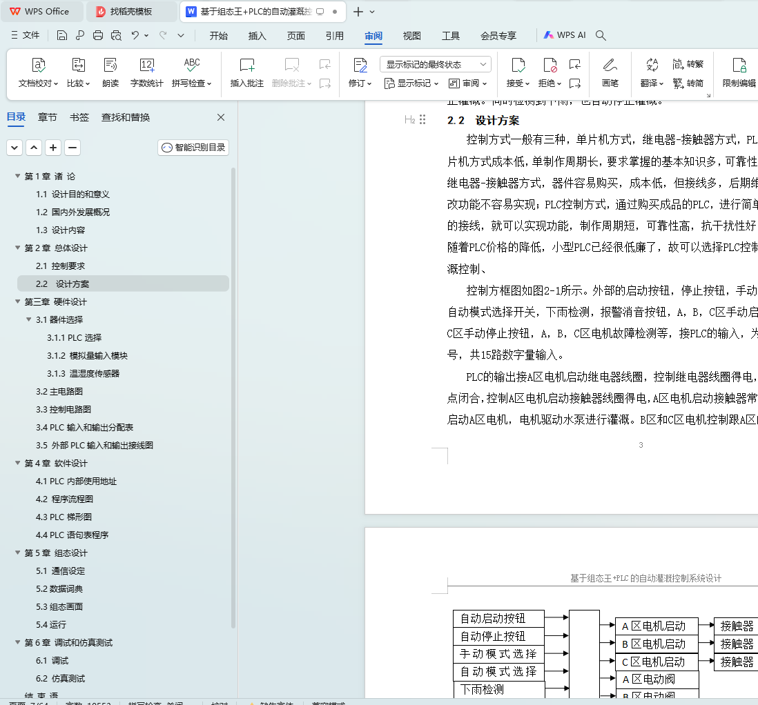
第1章 诸 论
1.1 设计目的和意义
1.2 国内外发展概况
1.3 设计内容
第2章 总体设计
2.1 控制要求
2.2 设计方案
第三章 硬件设计
3.1器件选择
3.1.1 PLC选择
3.1.2 模拟量输入模块
3.1.3 温湿度传感器
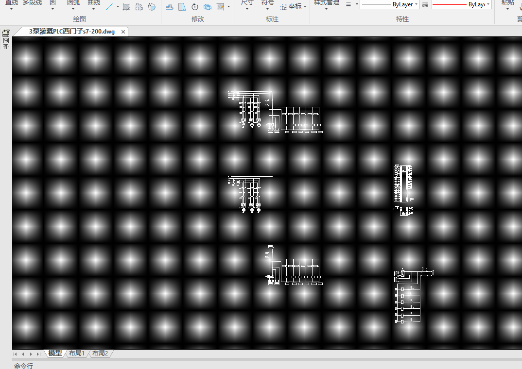
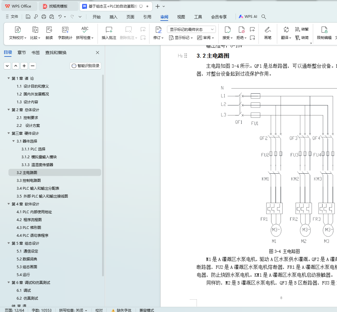
3.2主电路图
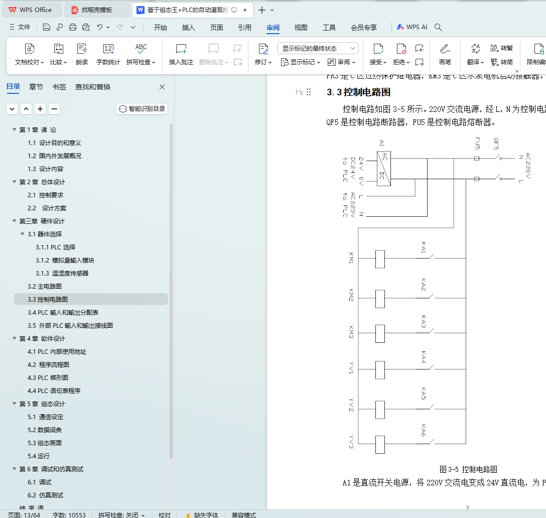
3.3控制电路图
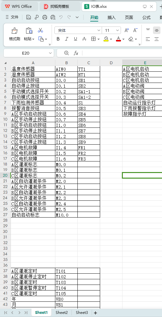
3.4 PLC输入和输出分配表
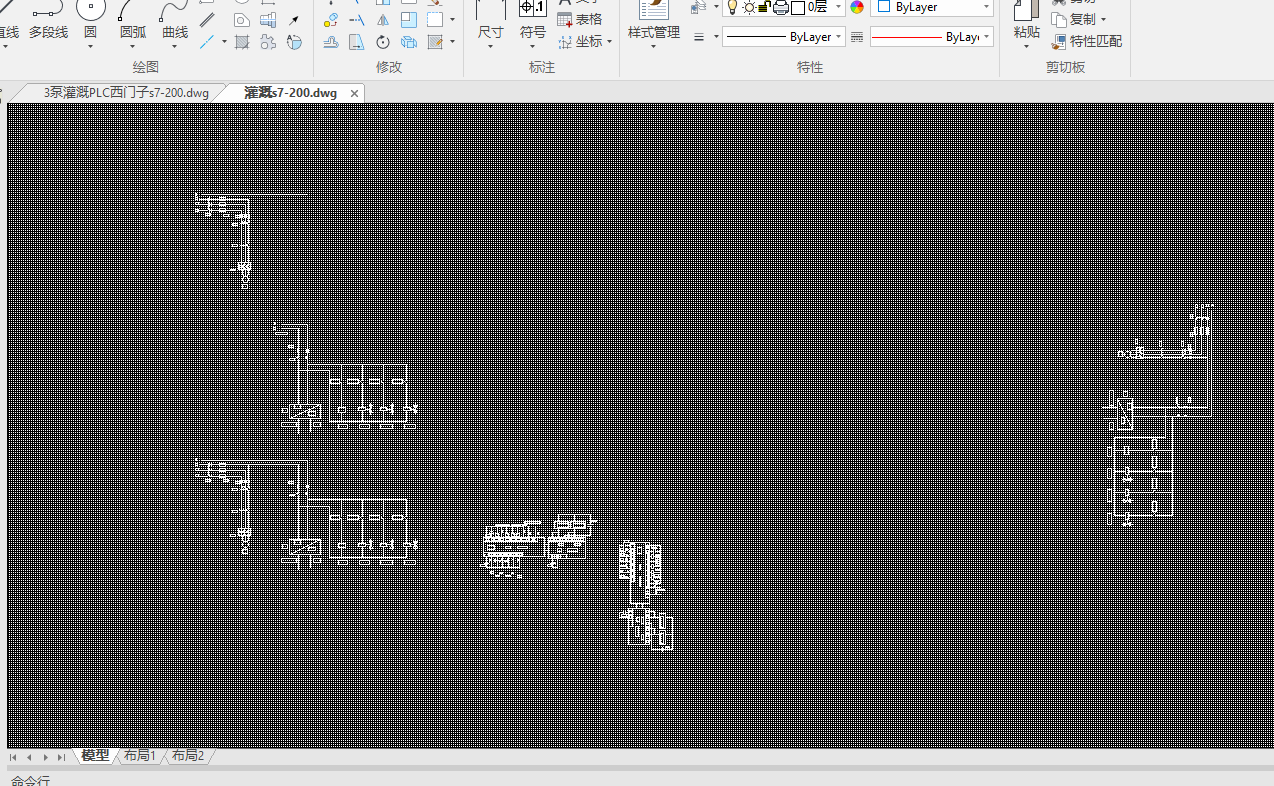
3.5 外部PLC输入和输出接线图
第4章 软件设计
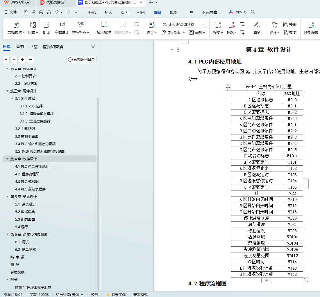
4.1 PLC内部使用地址
4.2 程序流程图
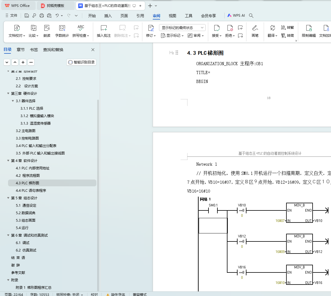
4.3 PLC梯形图
4.4 PLC语句表程序
第5章 组态设计
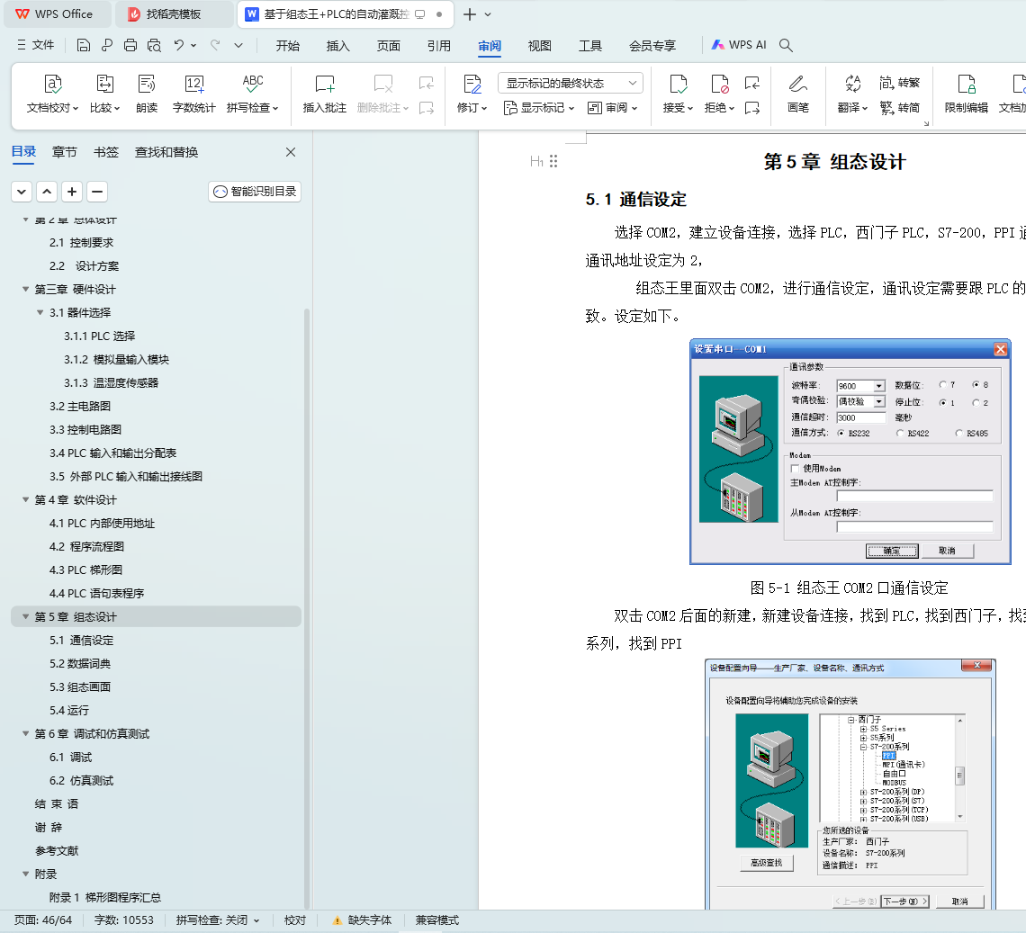
5.1 通信设定
5.2数据词典
5.3组态画面
5.4运行
第6章 调试和仿真测试
6.1 调试
6.2 仿真测试
结 束 语
谢 辞
参考文献
附录
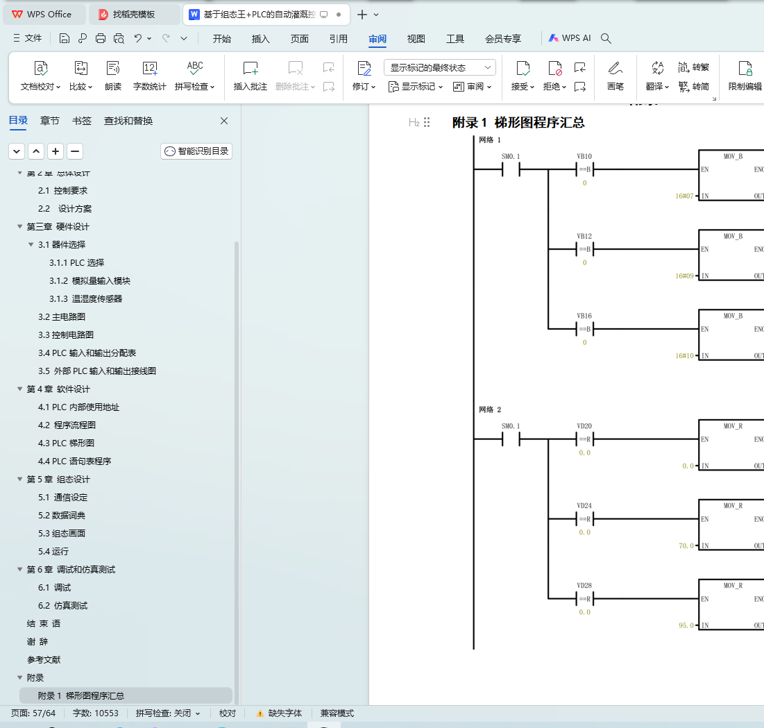
附录1 梯形图程序汇总
