Nie Y . Mechanical Structure Design of Automatic Riveting Machine[J]. New Technology & New Process, 2018.
NIE Yongzeng;Guangdong Province Technician College;
Mechanical structure design of automatic riveting machine
pick To: at present, more and more enterprises pay attention to the transformation and improvement of factory automation.Through research, it is learned that non-standard assembly automation will meet the production and automatic assembly requirements of more products in the future, especially personalized assembly requirements.In all links of mechanical engineering, mechanical design is the first step of mechanical production. It is necessary to optimize the design under various limited conditions and comprehensively consider various requirements, including the best working performance, the least manufacturing cost, the lowest energy consumption and so on.This paper takes the automatic riveting machine as an example to design the mechanical structure.The power part of automatic riveting is studied, and the gas-liquid booster cylinder is used to form the riveting pressure.The design of riveting die mainly determines the design of riveting part through parameterization, material selection and riveting clearance.The feeding part adopts vibrating plate combined with indexing plate.The modeling and assembly of mechanical structure are completed by SolidWorks software.The equipment studied can ensure the tightness requirements, ensure the size of non assembly position, ensure the stability and consistency of assembly parts, improve production efficiency and reduce production cost.
Key words: mechanical design, modeling, simulation, riveting, assembly and debugging, automation
With the continuous increase of labor cost, more and more enterprises pay attention to the field of factory automation, which also brings development opportunities to the industry.The development of mechanical automation equipment includes providing customers with integrated solutions from scheme, processing, assembly to commissioning.That is to provide customers with a complete set of solutions from product conception → scheme → modeling → drawing → processing → assembly → commissioning.
An enterprise specializing in the production and assembly of hardware products. In the production process, the demand for some parts is very large. In terms of 100000 pieces, the requirements for fastening and sealing of parts are high, and the requirements for replaceability are high.The part drawing and assembly of the "precision joint" produced by the enterprise are shown in Figure 1-1. The upper cover in the assembly is required to be riveted with the base.


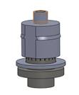
(a) Base (b) gasket (c) upper cover (d) assembly
Fig. 1 part drawing and assembly of "precision joint"
This part is an important part in the automatic production line, with high requirements for assembly process. Its high requirements are mainly reflected in three aspects: first, high requirements for fastening, second, high requirements for part deformation control, and third, high requirements for replaceability, otherwise it cannot pass the inspection.Relatively speaking, manual operation has high cost, poor product consistency and stability, and low production efficiency;Using industrial robot for assembly, its own visual sensing system can identify parts, and then assemble through manipulator, which saves some peripheral equipment, but the cost is high;In this plan, a non-standard automatic equipment is designed and manufactured to complete the assembly and riveting action, ensure the tightness requirements, ensure the size of non assembly position, ensure the stability and consistency of assembly parts, improve production efficiency and reduce production cost. The logical idea of mechanical design is shown in Figure 2. The modeling and simulation are completed by SolidWorks software, and the rationality of the design is verified through assembly.
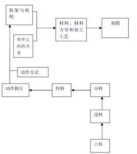
Figure 2 logical thinking of mechanical design
1、 Part analysis
The parts assembled this time belong to small parts. The size of the base and upper cover parts is less than 10mm, and interference assembly is adopted between them.The material of the part is Q235, the carbon content (WC%) is between 0.12% and 0.22%, belonging to low carbon steel, and the hardness is 36 ~ 40HRC.The assembly section is shown in Figure 3. The interference thickness is about 0.06mm and the assembly length is 2.4mm. Considering that there are few assembly actions and only three parts are involved, and considering the rational use of space and convenient layout, the rotary assembly machine is selected this time.

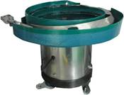
Fig. 3 assembly section Fig. 4 physical drawing of vibrating disk
2、 Selection of automatic feeding mechanism
Vibrator bowl is a kind of auxiliary feeding equipment for automatic assembly or automatic processing machinery, referred to as automatic directional sorting feeding device for short. It can automatically screen and sort disordered parts. The physical object is shown in Figure 4. Its model selects top plates of different sizes according to the size of parts. The size of top plates ranges from 80mm to 1000mm.The parts in this design are all micro parts, and the size of the base and upper cover parts is less than 10mm. At the same time, with reference to the cost performance of the vibrating plate in the market, the top plate size is selected asΦ140mm vibrating plate conveying gasket, and the top plate size is selected asΦ175mm vibrating disk conveying base and upper cover.ΦΦ
The positions of the discharge port of the vibrating disc and the feed rail are designed as shown in Figure 5. The discharge port of the vibrating disc is aligned with the feed rail, and the height of the vibrating feeder and the feed rail is adjusted through the height adjustment bolt (generally, the outlet height of the vibrator is 0.3mm higher than the feed port height of the rail).
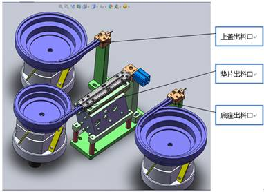
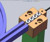
Fig. 5 design of discharge port and feed track of vibrating disk
The gasket is one of the assembly parts of the "precision joint", with a thickness of only 0.6mm and an outer diameter of only 8.5mm. The design of the conveying track is shown in Figure 6.The length of the straight track is 170mm. It is found in practice that the gasket will be stuck only by the strength of the vibrating plate and cannot move forward. Add a direct vibrator (as shown in Figure 7) to solve the problem of insufficient forward power of the gasket.
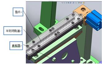
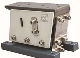
Fig. 6 feeding track of gasket (direct vibration / steel strip) Fig. 7 physical drawing of direct vibration device
3、 Design of indexing plate and rotary mechanism for "precision joint" assembly
Considering that the assembly of "precision joint" has three feeding positions, plus riveting assembly position and unloading position, the indexing plate has at least 5 positions. Considering that the manufacturing and operation are more convenient, another station is expanded. Therefore, the indexing plate is designed to have 6 positions and the rotation direction is clockwise.
For the intermittent rotation of the indexing disc, it is necessary to select an appropriate control mechanism.Stepping motor rotary mechanism, pneumatic indexing disc mechanism, ratchet pawl mechanism and cam splitter are four common rotary intermittent mechanisms. Through the comparison in Table 1 and the latest application in the market, the intermittent control function can be realized by using cam splitter and sensor combined with ordinary motor, as shown in Figure 8.
Table 1 Comparison of main technical and economic indexes of common rotary intermittent operating mechanisms
|
Serial number
|
Index comparison
|
Rotary mechanism of stepping motor
|
Pneumatic indexing disc
|
Ratchet pawl mechanism
|
Cam splitter
|
|
1
|
Driving torque
|
Small
|
large
|
large
|
large
|
|
2
|
positioning accuracy
|
commonly
|
high
|
low
|
commonly
|
|
3
|
Automation level
|
high
|
high
|
low
|
low
|
|
4
|
Working reliability
|
commonly
|
reliable
|
reliable
|
reliable
|
|
5
|
structure
|
complex
|
simple
|
simple
|
simple
|
|
6
|
Is the frequency adjustable
|
can
|
can
|
no
|
no
|
|
7
|
noise
|
Small
|
commonly
|
large
|
Small
|
|
8
|
running cost
|
high
|
commonly
|
low
|
low
|
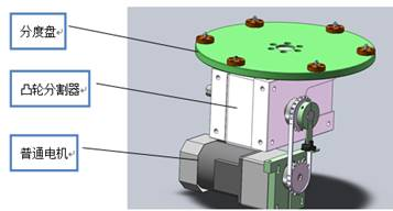
Figure 8 design index plate
4、 Selection of cylinder and gas-liquid booster cylinderDesign of and riveting part
In comprehensive consideration, appropriate cylinders are used for parts loading and unloading in three feeding positions and one unloading position, and 4 stations share 8 cylinders.Standard cylinder is used for front and rear movement, and thin cylinder is used for up and down movement to avoid interference, as shown in Figure 9.
In order to ensure the riveting effect, the assembly station is designed as a direct pressure gas-liquid booster cylinder, which takes the pure air pressure source as the power and uses the area ratio of large and small pistons of the supercharger to increase the low-pressure air pressure dozens of times into high-pressure oil pressure, so as to achieve the purpose of high-pressure output.Generally speaking, the stroke of gas-liquid booster cylinder is small, so it should be fully considered and utilized in stroke control to avoid invalid limit.In terms of shape control, ensure the quality of riveting without interference and damage to assembly parts. According to experience, 0.05mm is reserved on one side as the clearance for parts placement. The specific design is shown in Figure 10.
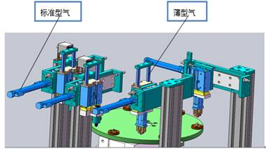
Figure 9 cylinder selection

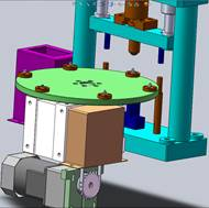
Figure 10 mechanical design of riveting part
5、 Modeling and assembly of mechanical structure of automatic riveting machine
In order to ensure that the whole mechanical structure is compact, the logical relationship is easy to sort out and the maintenance operation is convenient, the overall design is shown in Figure 11.The whole structure is designed, assembled and modified by SolidWorks software. Taking the rotary worktable as the center, the three feeding tracks are placed in parallel, the press riveting station is set opposite the three feeding tracks, the rotary worktable rotates clockwise, and the unloading station is located at the next position of the press riveting station.When assembling parts, the key to accurate assembly is to control the degree of freedom, including linear dimension, parallelism, perpendicularity, coaxiality, angle and so on.When interference occurs, first consider whether the assembly is correct. After eliminating the assembly problem, modify the part features until they are appropriate.
The overall layout and mechanical structure design of each system of the automatic riveting machine are carried out above, including base feeding mechanism, gasket feeding mechanism, upper cover feeding mechanism, indexing disc mechanism, press riveting mechanism, unloading mechanism, box, etc., which can meet the production needs, with simple and compact structure, reliable performance, flexible assembly and convenient operation.
In the follow-up, the electrical control design, PLC hardware control circuit design and PLC control program design, as well as the procurement, assembly and commissioning of spare parts are not repeated here. The trial production of the equipment is completed, as shown in Figure 12.
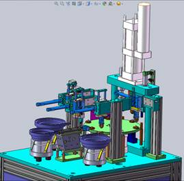
Figure 11 overall design
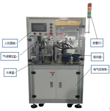
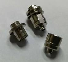
Fig. 12 equipment and finished products of automatic "precision joint" assembly machine
In short, the equipment improves the assembly efficiency of "precision joint", integrates the automation technology applied to the mechanical assembly control system, achieves rapid and continuous automatic assembly, avoids some situations caused by manual operation, such as insufficient riveting pressure, poor tightness, deformation of assembly parts, poor stability of assembly parts, and reduces the labor cost.In the future, assembly automation will develop to modularization, flexibility and automation to meet the requirements of high-yield variety production and automatic assembly.


