摘 要
目前常用的可调式焊接辊道架有两种:长轴式和组合式。组合式辊道架的使用寿命取决于焊缝的组成和长度,连续比不是连续的而是连续的,入口比为1和1。因此,焊接零件的应用符合要求。
在该方案的组合中,灵敏度和经济性是可调焊轮架生产的专用部件。一旦焊接技能和焊接工艺确定,选定的夹具布局开始实施管道焊接工艺。同时,焊接件的布置尺寸、焊料毛坯的生产工艺和生产精度是确定夹具定位技能、定位基准和夹具机构方案的紧张基础。
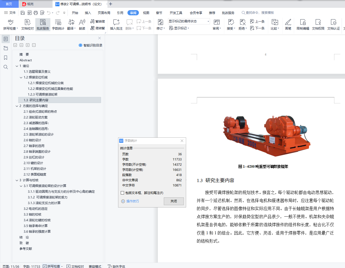
本文设计了一种组合式4T可变焊接轮架,并对轴、键等重要零件进行了检测。辊架布局简单,对焊接件适应性强。本文介绍了完整的组合式可调焊轮架,各部分的设计方案和重要部件的设计。这包括传动部件、工作齿轮、辅助装配和框架设计,以及轴、键、轴承等的实现。
关键词:焊接;滚轮架;组合滚轮架;传动部件;焊接件
Abstract
At present, there are two kinds of commonly used adjustable welding roller racks: long shaft and combination. Combined roller racks can last by the component and length of welds, continuous ratio not but continuous, and the entry ratio is 1 and 1. Therefore, the application of welding parts compliance.
In the combination of this plan, the sensibility and economy, which are the special components for the production of adjustable welding roller frame.Once the welding skills and welding process are determined, the selected fixture layout begins to implement the pipe welding process.At the same time, the layout size of welding parts and the production process and production accuracy of solder blank are the tense basis of determining the clamp positioning skills, positioning benchmark and clamp mechanism plan.
This paper designs a combined 4T variable welding wheel frame, and examines important parts like shaft and key.The roller frame layout is simple and highly adaptable to the welding parts.This paper talks about the complete combined adjustable welding roller frame, the plan of each part and the design of important parts.This includes transmission components, working gears, help assembly and frame design, and implementations of shafts, keys, bearings, etc.
Key words: welding; roller rack; combined wheel rack; transmission parts; welding parts
目 录
摘 要 I
Abstract II
1 绪论 1
1.1选题背景及意义 1
1.2焊接变位机械 1
1.2.1焊接变位机械的分类 1
1.2.2焊接变位机械应具备的性能 2
1.2.3可调焊接滚轮架 3
1.3 研究主要内容 5
2 方案的选择与确定 6
2.1组合式滚轮架的特点 6
2.2滚轮驱动方案 8
2.3减速器的选择: 8
2.4连轴器的选用: 9
2.5滚轮架滚轮的设计 10
2.6轴的设计 11
2.7轴承的选用 12
2.8轴承端盖的设计 13
2.9丝杠的设计 14
2.10键的设计 15
2.11机架的设计 15
2.12表面粗糙度 17
3 计算与校核 18
3.1可调焊接滚轮架的设计计算 18
3.1.1驱动圆周力与支反力的分析及中心角的确定 18
3.1.2 可调焊接滚轮架的受力 21
3.1.3滚轮支反力的计算 22
3.2电动机的选定 25
3.3轴的校核 26
3.4滚轮处键的校核 27
3.5轴承寿命计算 27
3.6轴承的强度计算 28
结 论 30
致 谢 31
参考文献 32
