Zhuoran Zhang Department of Electrical & Engineering Wuhan Polytechnic University Wuhan, China E-mail: Harry zzr@126.com
Zhe Mao, Hailing Wan Department of Electrical & Engineering Wuhan Polytechnic University Wuhan, China E-mail:maozhe998@ sina.com
Abstract―with the development of the modern society, the number of the vehicles in these cities has been increasing with an exponential speed; especially the private cars, putting a great pressure on urban transportation and parking slot. This article is mainly concerned about the entire structure, running procedure and electrical system design including hardware and program design ideas for lifting-traversing stereo garage, which will not only shorten the developing period but also orient parking to centralization and automation direction; Owning some reference value.
Keywords- Stereo Garage, Omron PLC, Design
Insufficient parking slots is resulted from the development of the cities, economy and transportation of the cities, the traditional garages are always making the use of the nature vacancy, in a community, the ratio between parking slots and residents is approximately 1:1, one parking slot for a family at least, in order to solve the contradiction that the parking slots using precious commercial land, the stereo mechanical garages with the advantage of the average parking slot takes of less area have been gradually in front of us. Compared with the traditional underground parking garage, the stereo garages have more advantages. First of all, the stereo garages can save more area. The traditional ways must be amassed driving path for vehicles, averagely, a car will take up 40m2 If we take multi-layers garage (6 layers) in to consideration, it is possible for 13 cars to park in the area of 50m2, which will save lots of land resources and land construction expenditure. Meanwhile, the stereo garage could guarantee the safety of the people and their cars. If there is anybody in the garage or the cars are not fully stopped, the system controlled by electrical equipment will not run either. It means that, in the scale of the management, the mechanical garage could separate the people and vehicles, which makes it more systematically. Especially for underground garages, install this kind of garage will save a large area of illumination system, so it is also emerge conservation and environment protection.
Ⅰ.THE CLASSIFICATION AND IMPLEMENT BACKDROP OF THE STEREO GARAGE
A.THE CLASSIFICATION OF THE STEREO GARAGE
According to the present development of the stereo garage, the stereo garage is including lifting-traversing, roadway stacking, vertical lifting, vertical circulating, circle level circulation; The concept of the stereo garage is all from automatic logistic material transmitting system. [3]The purpose of the stereo garage is to solve the parking problem in developed cities, that is make use of limited area to park more vehicles so as to save land resources of the cities and manage the static transportation of the urban. This article gives out a way to design lifting-traversing stereo garage based on Omron PLC CP1H, which could extend to solve relevant projects.
B. A BRIEF INTRODUCTION TO LIFTING-TRAVERSING STEREO GARAGE.
The modularization concept is imported in lifting-traversing stereo garage. It can be designed into two to five layers or half underground type, the number of the slot is from tens to hundreds. This kind of garage is suitable for both above ground and underground, the characteristics could be generalized as less occupation of land, simple structure, flexible configuration, lower cost in construction, decoration and fire protection and short period of construction; Safe and convenient for saving and taking cars; Smoothly operation, lower noise during running. [4] It is also appropriate for commercial, bureau and residential use. The safety equipment mainly is photoelectrical sensors, limiting displacement protector and emergency switch.
C. THE ENTIRE FRAME OF THE SYSTEM
As the fig. l representing, besides the central controller PLC, the stereo garage system could be divided into three sections: I. Mechanical System; It includes column, beam, carrying board, vehicle frame, hooks and etc. II. Electrical System; this section is the core of this article, which controls the whole system to operate. III. Touching Panel; it is the port from which operators and the system exchanging messages, operators could not only operate the system, but also in the situation of the malfunction, it could let operator enter the manual or debugging mode.
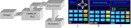
Figure 1. The structure of the system Figure 2. Touch Screen (Auto running and Manual)
• THE MAIN HARDWARE OF THE SYSTEM
We mainly use the Omron PLC CPH1, on considering the control requirement and the cost, we adopting CP1HX40DR-A PLC, the programming ways are ladder diagram or ST instruction list. The instruction length is 1 to 7 steps per instruction, each I/O relays has 1600 ports, USB 1.1 for communication.
The display part, we import screen of WEINVIEW MT6056i series, the screen material is TFT, 5.6 inches, and the resolution is 320x234, with USB2.0 port supporting downloading. The frequency of the CPU is 400 MHz, 128RAM.
D.THE SYSTEM STR UCTURE AND FUNCTIONS
The mechanical parts cooperating with electrical system are carrying board, hooks and chains. There are 6 slots on each layer besides 7 slots on the top layer, totally 37 slots, the purpose for one slot empty on each layer is that making enough space for carrying board to move. The carrying boards of the first floor only design to traverse, also the top floor carrying boards are only supposed to lift. The other carrying boards among these floors are designed to life and traverse. In this way, this system could achieve the saving and taking from any slots among these 6 layers.
In addition, this system has a touch screen system, which switches between auto run and manual debugging mode. Under the auto run mode, it could select a certain slot to accomplish saving and taking behavior, at the same time, monitoring the operation of the system. (Green words "System Running" in auto mode without malfunction). When failure occurs, the system seized and on screen flashing yellow failure code with red backdrop, with the help of the failure code, the professional operator could recognize and eliminate the failures promptly and accurately. On considering more authorities are given in manual debugging mode, to preclude unprofessional persons enter the mode by chance, before enter the mode, there is a cipher verification, in which the sequence could be set by ourselves. This would protect the system from potential dangers.
Figure 2 is the graph of system auto running, manual and debugging.
Ⅱ. THE COMPOSURE OF THE ELECTRICAL SYSTEM
A. STRONG ELECTRICITY SYSTEM
The strong power system includes power supply, protection and driving mechanism, here is electronic motors. Installing XJ3-D on the forepart of the power supply wire, which is used to protect phase sequence of the three-phase voltage, so that guarantee the right rotation of the motors. Moreover, the motors on some layers use the same three-phase voltage.
B.THE SET OF THE MOTORS
There are 6 traversing motors on the first layer, 6 traversing motors for 2 to 5 layers each, and so it is with lifting motors for 2 to 5 layers. The top layers have only 7 lifting motors. After setting the motors, mark every motor. For example, the motor driving the third slot of the second layer, we mark it with "23", the relay before the motor are named KM23. Here series connect all the motors' thermal protection, any motor's problem will stop the system. In this way, it has no influence on the stability of the system, but lowers the cost. At the same time, make it easier to find the problems. (What we need to do is press the thermal protection switch one by one).
C .WEAK POWER SYSTEM
The weak power system is also the control system, which are mainly the PLC mode and its 5 extended modules, also the sensors. As the figure below, on the right is the input part, DC 24V, on the left, is the output section, AC 220V, to connect with contactors and drive them. These device's functions have close relationships with the entire system's control requirements. On the above of the graph, the protection equipment are emergency switch, installed beside the touching panel, emergency only, trigger it, the system stops; Front and back photoelectrical sensors, which are used to detect people or unidentified objects breaking into the system, if this happens, the system would stop then response with photoelectrical failure, the goal is to protect the people and the vehicles. The phase sequence protection has been illustrated before; Over current protection normally activated under the motor stuck; All the margin switches series connected, cult the main power when any carrying board exceed the limiting position.
Limit switches including up ones and down ones or left and right limit switches. In order to achieve the controlling requirements, the level limit switches are installed on the both side of the each slot frame, while the vertical limit switches are installed on the chain which attached to the motor. It is necessary to point out that the first layer only installed down and left right limit switches, the top layer only installed up switches these switches could sense the position of the carrying boards, helping to finish the lifting and traversing control; Hook position sensors is to fix the vehicles and sense the slot empty or not.
The output points"00 04 05 06 07" are to select different phase for each layer, so control the motors' rotation ways.

Figure 3. PLC Modules (Segment)
There are other 4 extended modules, which only give more I/O ports to the system, similar to this main part.
Ⅲ. OPERATION PROCEDURE
A. TAKING PROCEDURE
As far as the first layer concerned, it is only designed to traverse, so as to make space to upper layer's carrying boards to move downward. So do the other layers, which are designed to traverse. When traversing meet the requirements, lifting mechanism will run to put the carrying board down, finishing the saving and taking procedure. During the procedure the photoelectrical sensors are open and will behave as fore part has explained. In figure 2A, is the taking condition, at this time "Loading" will flash until the taking procedure finishes.
When we enter "51", the system will distinguish whether the operation is a taking or a saving according to the hook of the 51 slot. Then prints the message responded to the state of the hook on the screen, the operator could confirm the operation or cancel it. On confirming, the 51 carrying board will wait for its downward boards to finish the traversing move then moving down. In addition, a timer is added to this control module in order to preclude level limit switches malfunction, resulting into the traversing move time up. If the time for traversing move exceeds the set time, the system will warn the operator "traversing move time up" which displays on the screen, the operator could check out the failure. The up limit switches are used to sense whether the carrying boards are stopped at their routine slots, which the level switches can't finish. Maybe one carrying board stuck between two layers. Only do all the upper layers' carrying boards stop at their routine slots, the selected carrying board's lifting move is activated. A timer is also set into the lifting control, with the same function as traversing timer. The elevator carries the vehicle down to the ground, release the hook, now the photoelectrical signal shut down, and waiting for the owners to take their vehicle. On driving away the vehicle and operator's confirming the photoelectrical signal resumes, the carrying board back to its slot from the down way.

Figure 4. The flowchart of the taking and saving procedure
B. SAVING PROCEDURE
The saving process is based on taking procedure, so they are familiar; the only difference is the hook move.
Ⅳ. SOFTWARE PROGRAMMING AND PROGRAMMING ENVIRONMENT
A.SOFTWARE PROGRAMMING ENVIRONMENT AND ITS LANGUAGE
In this system, we choose Omron CX-ONE 3.0 to program the PLC. The language for programming is classic ladder diagram. On considering the stereo garages are installed in different condition and requirement of different users, the scale of the stereo garages should be flexible, for example different layers or slots. In order to meet the different scales requirements, the program is modularized, only need to change the I/O ports, the logical relations in the ladder diagram are fixed. In this way, it is not only with highly compatibility but also shortens the period to develop relevant designs and make it easier to debugging and repair.
B.MODULARIZED PROGRAM
Conditional jumps are widely used in the programming; the entire program consists of different modules, on certain conditions, the program jumps.
As illustrated before, there are only two movements for a carrying board, lifting or traversing, beside the boards of first and top layers. The condition for the fifth could traverse is all the upper layers slots' up limiting switches closed. Then "Traverse OK" is activated, and then the program will make analysis of the operation until meet set conditions, the program jumps. For the lifting movements are always with the downward movements, so program the downward standards, the system will run. The entire program is programmed with this method, above the passage, is only a traversing OK and vertical move OK module. Similarly, modules of a fixed slot, for example slot "21". "21 Traversing Move", "21 Vertical Move"; for whole system, "Emergency Stop and Protection", "Button Select", "System Monitor" and "Debugging" modules, which cooperate with each other to accomplish the control and monitor.
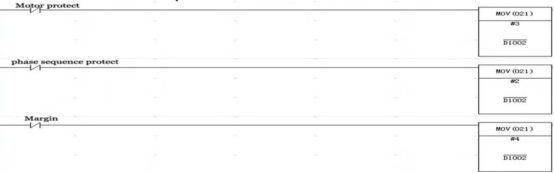
Figure 5. Monitoring and Display module (Segment)
Fig. 5 is the segment program of the monitoring module, all the motors' protection series connected, so are the phase sequence protection and margin switches. Any of them change; PLC will transfer messages to the screen, which displays. Meanwhile, cults off the main KM, the system stops.
Ⅵ.A BRIEF SUMMARY
This paper introduces lift shifting type six floors of three-dimensional garage design method based on Omron CP1HX40DR-A controller, completing the requirements of three-dimensional garage for city vehicle management toward the direction of automation and centralization. This design can be used to restore occupied pavement, reduce preempting, and ensure safety, in addition that it could reduce traffic congestion time, reducing the injury. On this basis, the problem has been thoroughly eliminated, including various vehicles disorderly stopping and parting in disorder, and the appearance of parking places with dirty, disorderly and poor, thus protecting vehicles away from lost, being damaged and stolen. Finally, the road is giving back to the vehicles and pedestrians, the lawn to the green space, the environment of the neat civilization life to the modern metropolis.
The development cycle has been greatly shortened, based on the design about three-dimensional garage design of PLC controller. This is also a kind of inevitable of the electrification, digital and automation advancement. The thoughts and methods of this design can be applied to other scale garage and relevant problems of design.
REFERENCES
[1] [1] Huo Gang. Application and programmer of the CP1HPLC. China Machine Press [M], 2009.1
[2] [2] Omron Power program. Omron Corporation (China), 2008
[3] [3] BoSen Ren.General situation of Chinese mechanical parking equipment. Celebrated manufacturers of parking equipment and peripherals directory [J] :PP5-7
[4] [4] Lekang Yu Dongxiao Zuo.The development of mechanical parking. [J] Technology and management of construction machinery. 1999 1:PP 30-32
[5] [5] Fuen Zhang „ Younai Wu.Principle „ design „ set up and maintenance of AC variable speed elevator. [M] China Machine Press 1999
