AUTOMATIC STEERING SYSTEM FOR ROTARY SNOW REMOVERS
Hirofumi HIRASHITA, Takeshi ARAI, Tadashi YOSHIDA
Advanced Technology Research Team, Public Works Research Institute 1-6,Minamihara, Tsukuba City, Ibaraki-Pref, Japan, 305-8516
Tel:+81-298-79-6757 Fax:+81-298-79-6732
E-mail:hirasita@pwri.go.jp, arai0333@pwri.go.jp, yoshida@pwri.go.jp
ABSTRACT: In cold and snowy parts of Japan, most snow is removed from roads by mechanical snow removers, and to deal with roadside conditions and guarantee safe operation, these machines are normally operated by two people: an operator and an assistant.
Work is in progress to develop automatic steering systems for snow removers in order to lighten the burden on snow remover operating staff and to reduce future labor requirements. This report describes an automatic steering system that incorporates three technologies: the lane marker system that has been developed in recent years as an ITS technology, RTK- GPS technology, and GIS technology. This steering system has been developed for rotary snow removers: the type of snow remover considered to be the most difficult to operate. The report also evaluates the three control methods based on the results of corroborative testing done using actual snow removers and outlines problems with these control systems that must be overcome to establish a working system.
KEYWORDS: Rotary snow remover, automatic steering, ITS, lane marker, GIS, GPS
1. INTRODUCTION
In cold snowy parts of Japan, snow is removed from roads by mechanical means to guarantee smooth winter road traffic. To guarantee that mechanical snow removal is performed appropriately according to the state of snow accumulation on road surfaces, a carefully planned attendance control method must be established and the machinery must be operated correctly.
The automatic steering system that has been developed is intended for use on rotary snow removers: a type with an operating method more complex than that of other types of snow removers. It has been developed to reduce the burden on snow remover operators and to lower future labor requirements.
2. BACKGROUND TO THE DEVELOPMENT
A rotary snow remover is operated by two people: an operator who drives the remover
and an assistant who controls the ejection of
while watching out for manholes or other level differences on its surface. The assistant ejects the snow while avoiding private property, homes, and other areas where snow disposal is forbidden (Photo 1).
The goal is to automate part of the vehicle operating work now performed by the operators to allow them to control the snow ejection now done by the assistants, permitting the introduction of one-man operation in the future.
 This report introduces positioning technology and control technology that form the foundation of the automatic steering system that has been developed, and presents an evaluation of the system based on the results of corroborative
testing performed with an actual snow remover and describes problems to be overcome to
the snow. The operator drives the machine along the curb on the shoulder of the road
complete a working system.
Photograph 1. Inside of a Rotary Snow Remover
3.  AUTOMATIC STEERING SYSTEM X
 The automatic steering system that has been developed automates the rotary snow remover steering operation that is one of the tasks of the operator.
3.1 Steering control of a rotary snow remover
The steering mechanism of a rotary snow remover differs from normal vehicles in that the front and back parts are linked by pins and articulating mechanisms are installed so that the vehicle can bend at the pins. The steering is controlled by the exact linearization method and by time scale transformation that are effective ways to control the course of a moving vehicle 1). This control method is represented by an equation of motion subject to non-holonomic constraint and is based on
Y
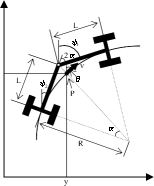
Figure 1. Coordinate System (Model of a Snow Remover)
If exact linearization and time scale transformation are done for equation (1) to perform status feedback control, the quantity of steering of the snow remover that is 1/2 of the steering angle �� is defined by the following equation.
non-linear control theory. But a snow remover slides laterally, because as it removes snow, it
a = tan-1{(f1 y + f2
tanq )L cos3 q }
(2)
 is subjected to lateral reaction force from the snow embankment
as shown by
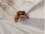
Photograph 2.
Sideways sliding is controlled by using the integrated servo system described
In equation (2), lateral sliding is not considered. In order to eliminate the steady-state deviation caused by lateral sliding, if the integrated servo system is used, the quantity of steering �� is represented by the following equation.
 a = tan-1 |L cos3 q {f3 ��(y - yref )v cosqdt + f1 y + f 2 tanq }|
below to treat this sliding as an
Photograph 2. Rotary Snow
⎝| ⎝ 0
J|]
(3)
 external distur- bance.
Remover Removing Snow
The symbol f is the control gain, and based on equation (3), f1 represents proportional gain, f2
(1) Course tracking control
Fig. 1 shows a model of the snow remover steering mechanism. In this figure, the distances from the connecting pin of the snow remover to the front wheels and to the rear wheels are represented by L. When the steering angle is represented by 2��, the course followed by the snow remover is an arc with radius R = L/tan��. When the course tangent direction speed vector at the center point P of the front wheels is represented by �� and the tangent direction angle by ��, the equation of motion of the point P can be written as follows.
represents derivative gain, and f3 represents integral gain. PID control was used to construct the system.
x�B = v cosq
y�B = v sin q

 q�B = v = v tan a
(1)
 Figure 2. Integrated Servo System Control Block
3.2 Positioning method
It is necessary to detect a vehicle��s present position and to have information that determines the direction to steer it in order to perform automatic steering.
The system that has been developed is equipped with two functions: the guidance method that use lane marker sensors to detect
To control steering with a single row of sensors (Fig. 3 on the left), the lateral differential and the azimuthal differential ym and �� m that are necessary for control by the target course
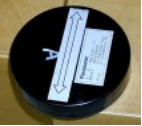
Photograph 3.
Radio Wave Marker
the vehicle��s position and the steering method
that uses GPS and GIS to detect the vehicle��s position.
3.3 Lane marker sensor guidance method
A lane marker sensor is a basic technology of the Advanced Cruise-Assist Highway System (AHS) developed for use as part of the Intelligent Transportation System (ITS). This technology includes lane markers buried at intervals under a road surface and vehicle mounted sensors that detect signals transmitted by these lane markers to guide the vehicle along the course formed by the markers. There are two versions of this system: the radio wave method and the magnetic method.
(1) Steering angle calculation logic

 It is assumed that the distance between the lane markers will not be constant, but can be varied according to the shape of the road and demands of the sensor side. Therefore, this system is equipped with two rows of sensors so that control can be performed even when the lane marker installation interval is not known until the rotary snow remover passes over them (Fig. 3).
coordinate system ��(xy) require information about the interval between the markers in addition to the sensor signal ym1 that is measured by the front vehicle fixed coordinate system ��f(xfyf). But with two rows of sensors (Fig. 3 on the right), the system can calculate the lateral differential and the azimuthal differential ym and ��m of the target course coordinate system ��(xy) by having two opposed sensors hold the two sensor signals ym1 and ym2 measured by the front vehicle fixed coordinate system ��f(xfyf) as it passed a marker until they pass the next marker, so that steering control can be performed even if the interval between markers was unknown.
(2) Radio wave marker sensor positioning method
With the radio wave method, an antenna inside the sensor on the vehicle transmits a 227.5 kHs radio wave towards the road and when a radio wave marker (Photo 3) receives this transmission, it returns a signal of double frequency of 455 kHz. A receiving antenna inside the sensor receives this return radio wave to detect the vehicle��s position (Fig. 6).
 The system detects the locations of the markers in the traveling direction by passing through the peak value. It detects the position in the lateral direction by calculating the distance between the antennas by the triangulation method
based on the difference in


 y ������y ��Lo����y ��y Lo��-1.0[m]
��/2.0����cos��
y ������y ��Lo����y ��y ��/Lm����cos��


 Lm��1.34[m]��Lo��-1.0[m]
the two receiving antennas 2).
Sensor
Figure 3. Lane Marker Sensor Guidance Method
(3) Magnetic marker sensor positioning method
 With the magnetic method, magnetic markers�� permanent ferrite magnets (Photo 5)��under the road surface produce
(1) Road GIS Road GIS is a data base of information concerning structures and traffic management used for road
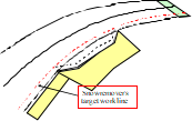
 Figure 5. Road GIS Data
magnetic fields and a magnetic sensor that detects magnetic field density installed on
Photograph 5. Magnetic Marker
maintenance. To develop this system, rotary snow remover target course information was created so that it can be handled as GIS data.
Operators of rotary snow removers remove
the vehicle determines the position of the vehicle based on the strength of each magnetic field.
 The magnetic field distribution of the magnetic marker shows the unimodality that treats the center of the marker as the maximum magnetic field strength. The magnetic flux densities of the vertical component (Bz) and the vehicle width direction component (Bx) of this magnetic field are detected by the magnetic sensor and the location of the marker is detected by calculating the distance between the sensor and the marker based on the previously stipulated Bx/Bz relational equation (Fig. 4) 3).

 Figure 4. Bx/Bz Relationship
3.4 GPS/GIS position detection method
A system based on GPS/GIS positioning detects the position of the vehicle to control its operation by comparing rotary snow remover position coordinate data received from a GPS satellite with position coordinates of linear data for the road provided in advance by road GIS.
snow to widen the bare road by driving their vehicles guided by the snow removal edge (Fig.
5) Because the snow removal edge is often the curb of the sidewalk along the sides of the road, the GIS data that was used is curb data.
(2) RTK-GPS
RTK-GPS, a system capable of high-precision positioning (error radius between 2 and 3 cm), consists of two GPS receiving antennae, one a fixed station and one a mobile station (on the snow remover). The fixed station transmits correction information based on GPS data it has received to the mobile station.
The system can perform almost real time positioning, because the GPS data is corrected at a rate of 20Hz.
4. CORROBORATIVE TESTING
Corroborative testing planned to simulate snow removal on a real road was carried out using a rotary snow remover equipped with the steering control system in Hokkaido in January and February 2002.
The corroborative testing was performed in order to evaluate the applicability and practicality of each automatic steering method under the behavior characteristic of a snow remover on an actual road (low speed, lateral sliding).
4.1 Outline of the corroborative testing
(1) The rotary snow remover
The body of the rotary snow remover was the medium size model (2.2 m wide) used most frequently on national highways, and the body constructed according to normal specifications was partially modified (Fig. 6).
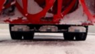
 Fig. 6 Rotary Snow Remover Equipped with an Automatic Steering Support Function
Table 1. Lateral Discrepancy for Each System (Example)

 Stand-alone operation (working speed 4 km/h, quantity of deviation of front sensor)
 Unit m
(2)  Corroborative test course
The corroborative test course consisted of straight sections, curves, (R 30 m), and intersections (R 12 m) so that it reproduced conditions on national highways. Its lane marker intervals were 2.0 m and 1.5 m.


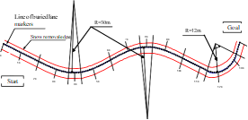


 The rotary snow remover work conditions were identical to those of actual work, with the work done at two speeds, 4 km/h and 0.5 km/h 4). Snow banks were prepared to provide the work load and lateral sliding that occur when a remover is used to widen the cleared part of a road.


 Figure 7. Layout of the Test Course
4.2 Results of the corroborative testing
The testing corroborated the lane marker sensing (radio wave and magnetic) guidance methods and the GPS/GIS positioning method.
Because the steering control system developed is a system that follows a preset target course, its control performance was evaluated as the quantity of deviation of the snow remover from its target course (quantity of lateral deviation). Table 1 shows the quantities of lateral deviation from the test results organized by method.
138
This table shows that overall, the quantity of deviation and the standard deviation were both small on the straight sections, but both were higher on curves and at intersections. This difference is presumably a result of the fact that in sections with a small radius of curvature, a larger quantity of steering is performed and the snow removal load is more likely to cause lateral sliding.
By method, the GPS/GIS method is superior to the lane marker method. Because the former method achieves almost real time positioning and steering control of almost 20Hz, it can respond instantly to lateral sliding to reduce the quantity of deviation. With the latter, steering is delayed because the system cannot detect lateral sliding where there are no signals between lane markers, resulting in a large quantity of lateral deviation. Therefore, testing was done by, in addition to correcting lateral sliding with the sensor, providing the coordinates of the next marker (course information) as the sensors passed the markers.
The resulting lateral sliding distribution reveals that as shown in Fig. 8, ��2 ��(��: standard differential) at this time was �� 57 cm without course information, and it was �� 31 cm with course information: a big improvement that brings its precision extremely close to that of the GPS/GIS method.
No gap in performance between the speeds 4 km/h and 0.5/h was observed.
Figure 8. Lateral Deviation With and Without Course Information (Radio Wave Method)
5. CONCLUSIONS AND FUTURE CHALLENGES
It has been confirmed that automatic steering systems using lane markers or GPS, GIS, etc. can achieve a generally practical level of control of normal snow removal work by rotary snow removers. But in order to establish practical working systems, the following challenges must be resolved.
(1) Testing of the GPS/GIS method showed that its detection precision temporarily fell even in open spaces. It is assumed that this happened when the GPS satellites were concentrated in a narrow range. And during testing of the radio wave marker method, unpredictable behavior thought to be an effect of the high output transmitter on the vehicle was observed. It is necessary to provide a function that automatically stops operation without the intervention of the operator when such abnormal operating signals are produced.
(2) And as in the GPS/GIS case, it is necessary to improve the precision of control by the lane marker method by entering the lane marker coordinates to the snow remover system in advance to provide it with course information. It is also essential to record passage over each marker each time the system passes over the markers.
In recent years, various organizations have attempted to apply information technology (IT) to improve construction machinery. As seen in those cases, the information handled in this case cannot be applied to other systems unless its use is premised on standardization. Because the rotary snow remover developed by this project requires new road infrastructure such as lane markers, road GIS data, and communication systems and its communication standards must be standardized, its development has been harmonized with communication technologies in the ITS field. The authors hope that this research and development will contribute to introducing it as a working system.
In conclusion, the authors wish to express their deep gratitude to the Hokuriku Regional Development Bureau and the Hokkaido Regional Development Bureau of the Ministry of Land, Infrastructure, and Transport whose members helped with the corroborative testing and to everyone who helped with the fabrication of the system and the testing work.
REFERENCES
1) Sanpei M. Ito T.: Path planning and path tracking control of wheeled vehicles using nonlinear system theory��parking control using forward and backward movement, Collected Reports of the Institute of Systems, Control, and Information Engineers, Vol. 6, No. 1, pp. 37 to 47, 1993
2) Handa S., Nakazuka A., Tanji Y.: Lane marker system, Matsushita Technical Journal, pp. 45 �C 49, October 2001
3) H. Suzuki: Development of Lane Marker System in AHSRA, 6th World Congress on Intelligent Transport Systems, November 1999.
4) Fourth edition of the Road Snow Removal Handbook: edited by the Japan Construction Mechanization Association, pp. 131

 y
y
 And to further improve control precision (reduce the quantity of deviation), it is necessary to strive to quantify disturbance such as lateral sliding and the snow removal load etc. of the snow remover and to perform simulations after increasing the degree of detail of the model of snow removal work by a rotary snow remover.