ify: inter-ideograph;">as very precise position state sensors.
control hardware
(microcontroller)
one complete finger
fixation frame
Figure 3: Top view of the KDH II
Proceedings of the IEEE-RAS International Conference on Humanoid Robots
Copyright 2001
 For sensing the forces applied to an object by a
finger a prototype of a 6 dimensional force torque
sensor has been developed (see figure 5). It can be
used as the last finger limb and is equipped with a
spherical finger tip. It is able to grasp light objects
as well as relatively heavy objects up to 3 to 5 kg.
The sensor is able to measure forces in x- y- and z-
direction and torques around these axes.
Additionally 3 colinear laser triangulation sensors
are mounted in the palm of the KDH II (see
figure 4) [11]. Because there are three such sensors
not only the distances of 3 single points can be
measured, but also the distance and orientation of
the surface of a grasped object, if the shape of the
object is known. This object pose sensor works
with a frequency of 1 kHz which allows the
detection and avoidance of a slipping object.
loop control in software are executed in parallel
for multiple fingers as well as for the object.
• Small physical size is needed to be able to
integrate the control system into the
manipulation system.
• Short electrical connections between the control
system and the actuators and sensors should be
used. This is especially relevant for the sensors
because otherwise massive interference might
disturb the sensor signal.
4.1 Control hardware
To cope with the requirements the control hardware
is usually distributed among several specialized
processors. For example the input/output on the
lowest level (motors and sensors) can be handled
4
Control system
by a simple microcontroller, which is also of small
size and thus can be integrated more easily into the
The control system of a robot hand determines
which of the potential dexterous skills provided by
the mechanical system can actually be exploited.
As mentioned before the control system can be
subdivided in the control computer or hardware and
the control algorithms or software.
The control system must meet several conflicting
requirements:
Figure 5: 6 DOF force torque sensor with strain
gage sensors used as the last finger limb
of the KDH II
• Many input/output resources like actor or
sensor signals must be attached. For example
for a minimum hand with 9 degrees of freedom,
at least 9 analog outputs to the motors and 9
inputs from angle encoders must be estimated.
With force and tactile sensors for every finger
and additional object state sensors the number
of inputs quickly increases to several dozens.
• Quick reactions in real-time to external events
are required. If for example a slipping of the
grasped object is detected immediate counter
measures must be taken.
• High computing power for several different
tasks must be available. For example path
planning, coordinate transformations, closed
manipulation system. But the higher levels of
control need more computing power and the
support of a flexible real time capable operating
system. This can be achieved most easily with PC-
like components.
Therefore the control hardware often consist of a
non-uniform, distributed computing system with
microcontrollers on the one end and more powerful
processors on the other. The different computing
units then have to be connected with a
communication system, like for example a bus
system.
4.2 Control software
The control software of a robot hand is quite
complex. Several fingers must be controlled in real-
time and in parallel while new trajectories for the
fingers and the object must be planned at the same
time. Therefore it is necessary to reduce the
complexity by dividing the problem into sub
problems.
Another aspect concerns software development. As
a robotic hand is usually a research project for most
of it's lifetime, the programming environment, like
user interface, programming tools and debugging
facilities, should be powerful and flexible. This can
only be achieved if a standard operating system is
used.
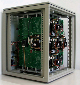
Figure 6: control hardware architecture of the KDH II
Proceedings of the IEEE-RAS International Conference on Humanoid Robots
Copyright 2001


 The usual hierarchical control system approach
used in robotics has to be trimmed to fit the special
needs of the controlling of a robot hand.
4.3 The control system of the Karlsruhe
Dexterous Hand II
As suggested in section 4.1 a distributed approach
to the control hardware was taken for the Karlsruhe
Dexterous Hand II (KDH II) (see figure 6) [8]. One
microcontroller is used to control the actuators and
sensors of one finger respectively. An additional
microcontroller is used for the object state sensor
(laser triangulation sensors). These
microcontrollers (the outer boxes to the left and
right in figure 6) are mounted directly on the hand,
thus short electrical connections to the actuators
and sensors are guaranteed. The microcontrollers
are connected to the main control computer by
serial bus systems (CAN-bus).
The main control computer of the KDH II (the light
grey box in figure 6, and figure 7) is implemented
as a parallel computer consisting of 6 industrial
PCs (PC104 standard). These PCs are arranged in a
2D-plane. Neighboring PC-modules (a PC has at
most 8 neighbors) use a dual ported RAM (DPR)
for fast communication (the dark grey boxes in
object movement commands are received from the
superior robot control system and used for a fine
planning of the object path. According to the
generated object path feasible grasps (possible
grasp points for fingers on the object) are planned.
Now that the grasps and the object movements are
known the trajectories for each finger are planned
by the finger path planning and forwarded to the
real-time capable part of the system.
If an object is already grasped, then the finger
movement paths are forwarded to the object pose
controller. This controller controls the actual object
pose, determined by the gripper and object state
sensors, to reach the desired object pose. If a finger
is not attached to an object, then it's movement path
is forwarded directly to the hand controller.
The hand controller coordinates the movements of
all fingers by forwarding correspondent desired
finger positions to all finger controllers. These in
turn drive the finger actuators with the help of the
finger sensors.
local object path planning
figure 6).
One PC is used to control a finger respectively.
One PC controls the object state sensors and
finger path planning
object movement
object pose controller
free movement
calculates the object's position. The remaining PC
is placed such that it neighbors all the previously
hand controller (finger coordination)
mentioned PCs. It is used for the coordination of
the whole control system
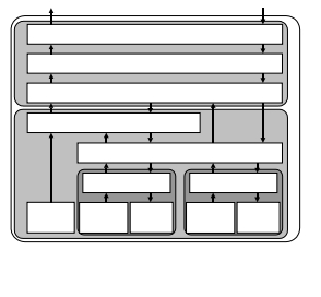
The structure of the control software reflects the
control hardware architecture. It is shown in
figure 8.
object
sensors
finger controller 1
finger 1 finger 1
sensors actuators
Fing
...
finger controller n
finger n finger n
sensors actuators
Fing
On the three top levels of the local hand control
system an on-line planning is performed. Desired
Figure 8: local hand control system of the
Karlsruhe Dextrous Hand II
Figure 7: parallel main computer used to control the
KDH II
To validate the capabilities of the Karlsruhe
Dexterous Hand II two demanding manipulation
problems were chosen. One problem is the on-line
controlling of the pose (position and orientation) of
a grasped object under external influences. Here
the hard real-time conditions reveal the controlling
capabilities of the approach chosen.
For the other problem a grasped object must be
rotated around arbitrary angles, which can only be
achieved with regrasping. This reveals the
capability of the Karlsruhe Dexterous Hand II to
perform very complex manipulation tasks.
5.1 Object pose control
The objective of the object pose controller is to
correctly position and orientate a grasped object to
fit a given trajectory. This task must be achieved
on-line under real-time conditions and in spite of
internal variations and external disturbances.
Proceedings of the IEEE-RAS International Conference on Humanoid Robots
Copyright 2001
 Internal variations are for example the rolling of the
spherical fingertips on a grasped object during
object movements in the workspace of the hand.
Figure 9: additional displacement due to rolling
Figure 10: additonal undesired tilt due to rolling
of the shperic fingertips on the object
This rolling is shown in figure 9 and figure 10. It
can result in an undesired additional displacement
or in an undesired tilt of the object. These object
pose errors are hard to estimate in advance.
Therefore the input of an object pose sensor is
needed to correct the errors. For the Karlsruhe
Dexterous Hand II the three laser triangulation
sensors were used for this purpose.
Figure 11 shows the undesired tilt of the object
according to figure 9 quantitatively when no object
pose control is used. The lower diagram shows the
desired trajectory over time in x-direction, while
the upper diagram shows the resulting undesired
rotation (tilt) of the object.
In figure 11 the tilt of the object is significantly
reduced due to the enabled object pose control. In
the upper diagram the rotation of the object
remains essentially constant, as desired.
An object pose controller is also necessary to
compensate external disturbances. For example
collisions of the robot (arm, hand or fingers) or the
grasped object with the environment might result in
the slipping of the grasped object. This might even
lead to the loss of the grasped object and is
therefore not acceptable. In order not to lose the
object in such situations the slipping must be
detected and a quick reaction must be performed to
stabilize the object pose.
To verify the capability of the Karlsruhe Dexterous
Hand II control system to cope with this kind of
Figure 11: Object tilt without object state control
Figure 13: Slipping experiment: actual object
position in x-direction (direction of
slipping)
Figure 12: Reduced object tilt with object state
control
Figure 14: Slipping experiment: actual object
orientation about z axis
Proceedings of the IEEE-RAS International Conference on Humanoid Robots
Copyright 2001


 disturbances the following experiment was made:
While an object was grasped the finger-contact-
forces were constantly reduced until the object
began to slip. After the slipping was detected with
the laser triangulation sensor the object pose
controller took measures to recontrol the object to
the desired pose.
Figure 13 and figure 14 show an example of such
an experiment. Especially figure 13 shows that the
object slipping starts quite abrupt and is quite fast.
But the object pose controller reacts fast enough to
detect and compensate the slipping so that the
object position (here: especially in x-direction, the
direction of the slipping) and the object orientation
is restabilized to the original desired value quickly.
5.2 Regrasping
Although the Karlsruhe Dexterous Hand II is very
flexible it can not perform every desired object
manipulation at first go. This originates from the
fact that the fingers are very small compared to
'normal' industrial robots and therefore only have a
limited workspace. If an object is grasped with the
fingers it can at first only be manipulated in a
subspace of all the fingers workspaces. The
a)
c)
e)
b)
d)
f)
condition for a feasible manipulation is that all the
contact points must be permanently inside the
workspace of the contacting finger. This limits the
feasible manipulations considerably.
To overcome this limitation a so called regrasping
operation must be performed. I.e. when a contact
point reaches the limitation of the contacting finger,
that finger must be detached from the object and
reattached at a new contact point. This is only
possible reliable by a hand with more than 3
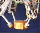
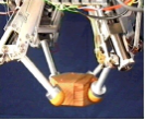
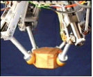
Figure 15: rotation of a nut shaped object with
regrasping.
fingers. By cyclically regrasping all fingers
arbitrary object manipulations can be performed.
An example of such a manipulation where
regrasping is necessary is rotation of the grasped
object about large angles. Figure 15 shows a
sequence of photographs of the Karlsruhe
Dexterous Hand II rotating a nut shaped object.
The object is rotated about its vertical axis. In the
sequence a) to c) all fingers are attached to the
object and it is rotated by coordinated movements
of all four fingers. The sequences d) to f) show a
regrasping action for one single finger. In d) the
fingers have reached their workspace limits and the
coordinated movements of all fingers is stopped.
The finger to the front left is detached from the
object and moved separately to another contact
point. In f) the finger is reattached to the object and
another finger can be repositioned (not shown).
a)
c)
e)
b)
d)
f)
After all fingers are repositioned the coordinated
rotation operation continues.
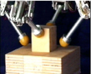
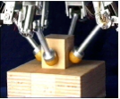
Depending on the circumstances the Karlsruhe
Dexterous Hand II is also able to regrasp several
fingers simultaneously. This speeds up the
regrasping process but is only possible if the
grasped object is in contact with the environment,
like for example a nut on a screw or a peg in a hole.
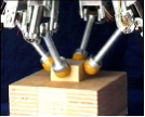
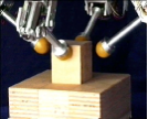
Figure 16: pulling a peg out of a hole with
regrasping
Figure 16 shows a sequence of photographs of the
Karlsruhe Dexterous Hand II. pulling a peg with a
square base out of a hole. The peg is pulled out half
way in sequence a) to b) then the left and the right
finger are detached and repositioned, both fingers
Proceedings of the IEEE-RAS International Conference on Humanoid Robots
Copyright 2001


 at the same time, sequence c) to e). After that the
finger in the front and back are also repositioned,
sequence f). After that the whole peg can be pulled
out of the hole for further manipulations (not
shown)
[3]
for a three fingered robot gripper, Proc. of the
1996 IEEE/RSJ Int. Conf. on Intelligent
Robots and Systems, IROS, Osaka, Japan,
Nov. 1996
R. Menzel, Konstruktion und Regelung einer
6
Conclusion
Hand, Fortschritt-Berichte VDI-Reihe 8 Nr.
451,1995
To be able to perform dexterous fine manipulations
with a robot hand a suitable mechanical system and
control system is necessary. The introduced
criterions for these systems must be considered as
shown in this paper. This was done successfully for
the Karlsruhe Dexterous Hand II. This robot hand
is capable of grasping a wide variety of objects of
different shape, size and weight. The pose of a
grasped object can be controlled reliably, even
under external disturbances. Additionally complex
fine manipulations, like regrasping, are possible
with this system.
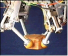
The novel hand to be built in the context of the
'humanoid robots' special research area, will be
anthropomorphic and mechanically based on a very
different concept called fluidic actors (see
figure 17) developed at the IAI in the Karlsruhe
research center [12]. However the principal
structure of the control software will be adapted
and used for the novel hand.
Figure 17: fluidic hands developed at the IAI
7 Acknowledgements
This paper is based on research done at the Institute
for Process Control and Robotics Prof. Dr.-Ing. H.
Wörn, as well as on the research done at the
[4]
[5]
[6]
[7]
[8]
[9]
[10]
[11]
[12]
J.K. Salisbury, Articulated Hands: Force
Control and Kinematics Issues, Phd thesis,
Stanford University, 1982
G. Hirzinger, Mechatronik-Konzepte nicht
nur für die Raumfahrt, Deusche
Forschungsanstalt für Luft- und Raumfahrt,
Hannover Messe, 1996
W. Paetsch, Exemplarische Untersuchungen
zu mehrfingrigen Robotergreifern: Aufbau-
Regelung- Systemintegration, Fortschritt-
Berichte VDI-Reihe 8 Nr. 363, Düsseldorf,
1993
B. Magnussen, Infrastruktur für Steuerungs-
und Regelungssysteme von robotischen
Miniatur- und Mikrogreifern, Fortschritt-
Berichte VDI Reihe 8, Nr.567, Düsseldorf:
VDI-Verlag, 1996
T. Fischer and H. Woern, Structure of a robot
system: Karlsruhe Dexterous Hand II,
Mediterranean Conference on Control and
Systems, 1998
Th. Doersam and Th. Fischer, Using Fuzzy
Controllers for the Karlsruhe Dexterous Hand,
The Int. Symposium on Intelligent Robotic
Systems, SIRS, Lisbon, Portugal, 1996
Th. Fischer and J. Seyfried, The new
Karlsruhe Dexterous Hand II, Int. Sym. on
Intelligent Robotic Systems, 1997
T. Fischer and H. Woern, Multifinger
Grippers for Human-like Robots in Industry,
World Multiconference on Systemics
Cybernetics and Informatics, Orlando,
Florida, 1999
S. Schulz, C. Pylatiuk, and G. Bretthauer. A
new class of flexible fluidic actuators and
their applications in medical engineering. In
at- Automatisirungetechnik 47, pages 390-
395, 1999
Institute for Applied Computer Science Prof. Dr.-
Ing. G. Bretthauer.
References
[1] Th. Doersam and Th. Fischer, Aspects of
Controlling a Multifingered gripper,
International Conference on Conventional and
Knowledge-based Intelligent Electronic
Systems, 1997
[2] Th. Doersam and P. Dürrschmied,
Compensation of friction in mechanical drives
Proceedings of the IEEE-RAS International Conference on Humanoid Robots
Copyright 2001
,

 Mechanical System and Control System of a Dexterous
Robot Hand
Dirk Osswald, Heinz Wörn
University of Karlsruhe
Department of Computer Science
Institute for Process Control and Robotics (IPR)
Engler-Bunte-Ring 8 - Building 40.28
D-76131 Karlsruhe
email: osswald@ira.uka.de , woern@ira.uka.de
Abstract: In recent years numerous robot systems
with multifingered grippers or hands have been
developed all around the world. Many different
approaches have been taken, anthropomorphic and
non-anthropomorphic ones. Not only the
mechanical structure of such systems was
investigated, but also the necessary control system.
With the human hand as an exemplar, such robot
systems use their hands to grasp diverse objects
without the need to change the gripper. The special
kinematic abilities of such a robot hand, like small
masses and inertia, make even complex
manipulations and very fine manipulations of a
grasped object within the own workspace of the
hand possible. Such complex manipulations are for
example regrasping operations needed for the
rotation of a grasped object around arbitrary
angles and axis without depositing the object and
picking it up again. In this paper an overview on
the design of such robot hands in general is given,
as well as a presentation of an example of such a
robot hand, the Karlsruhe Dexterous Hand II. The
paper then ends with the presentation of some new
ideas which will be used to build an entire new
robot hand for a humanoid robot using fluidic
actuators.
Keywords: Multifingered gripper, robot hand, fine
manipulation, mechanical system, control system
with such a robot hand system. This new hand will
be built by the cooperation of two institutes, the
IPR (Institute for Process Control and Robotics) at
the University of Karlsruhe and the IAI (Institute
for Applied Computer Science) at the Karlsruhe
Research Center. Both organizations already have
experience in building such kind of systems, but
from slightly different points of view.
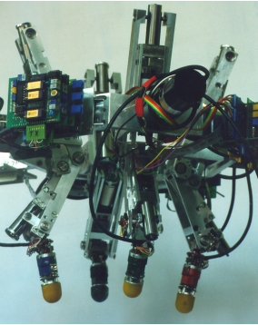
The 'Karlsruhe Dexterous Hand II' (see figure 1)
built at the IPR, which is described here in detail, is
a four fingered autonomous gripper. The hands
built at the IAI (see figure 17) are built as
prosthesis for handicapped people.
The approach taken so far will be presented and
discussed in the following sections, as it founds the
basis for the novel hand of the humanoid robot.
The special research area 'Humanoid Robots'
founded in Karlsruhe, Germany in July 2001 is
aimed at the development of a robot system which
cooperates and interacts physically with human
beings in 'normal' environments like kitchen or
living rooms. Such a robot system which is
designed to support humans in non-specialized,
non-industrial surroundings like these must, among
many other things, be able to grasp objects of
different size, shape and weight. And it must also
be able to fine-manipulate a grasped object. Such
Figure 1: Karlsruhe Dextrous Hand II from IPR
great flexibility can only be reached with an
adaptable robot gripper system, a so called
multifingered gripper or robot hand.
The humanoid robot, which will be built in the
above mentioned research project, will be equipped
Proceedings of the IEEE-RAS International Conference on Humanoid Robots
Copyright 2001
 2 General structure of a robot hand
A robot hand can be split up in two major
subsystems:
• The mechanical system
• The control system
The mechanical system, further described in section
3, can be subdivided into:
- The mechanical design
- The actuator system
- The sensor system
And the control system described in section 4
consists at least of :
- The control hardware
- The control software
For each of these parts we will describe the
considerations for a robot hand in general and then
present the exemplary implementation in the
Karlsruhe Dexterous Hand II.
3 Mechanical system
The mechanical system describes how the hand
looks like and what kind of components it is made
of. It defines the mechanical design, e.g. the
number of fingers and the kind of materials used.
Additionally actuators, e.g. electric motors, and
sensors, e.g. position encoders, are settled.
3.1 Mechanical design
The mechanical design determines the fundamental
'dexterousness' of the hand, i.e. what kind of
objects can be grasped and what kind of
manipulations can be performed with a grasped
object. Three basic aspects have to be settled when
designing a robot hand:
• The number of fingers
• The number of joints per finger
• The size and placement of the fingers
To be able to grasp and manipulate an object safely
within the workspace of the hand at least 3 fingers
are required. To achieve the full 6 degrees of
freedom (3 translatory and 3 rotatory DOF) for the
manipulation of a grasped object at least 3
independent joints are needed for each finger. This
approach was taken for the first Karlsruhe
Dexterous Hand [1,2]. However, to be able to
regrasp an object without having to release it and
then pick it up again, at least 4 fingers are
necessary.
To determine the size and the placement of the
fingers two different approaches can be taken:
• Anthropomorphic
• Non-anthropomorphic
It then depends on the objects to manipulate and on
the type of manipulations desired which one is
chosen. An anthropomorphic placement allows to
hand to the robot hand. But the different sizes of
each finger and their asymmetric placement makes
the construction more expensive and the control
system more complicated, because each finger has
to be treated separately.
When a non-anthropomorphic approach is taken
most often identical fingers are arranged
symmetrically. This reduces the costs for the
construction and simplifies the control system
because there is only one single 'finger module' to
be constructed and controlled.
3.2 Actuator system
The actuation of the finger joints also has a great
influence in the dexterousness of the hand, because
it determines the potential forces, precision and
speed of the joint movements. Two different
aspects of the mechanical movement have to be
considered:
• Movement generation
• Movement forwarding
Several different approaches for these aspects are
described in the literature. E.g. the movement can
be generated by hydraulic or pneumatic cylinders
[3] or, as in most cases, by electric motors.
As the movement generators (motors) are in most
cases to big to be integrated in the corresponding
finger joint directly, the movement must be
forwarded from the generator (most times located
in the last link of the robot arm) to the finger joint.
Again different methods can be used, like tendons
[4,5,6], drive belts [1,2] or flexible shafts. The use
of such more or less indirect actuation of the finger
joint reduces the robustness and the precision of the
system and it complicates the control system
because different joints of one finger are often
mechanically coupled and must be decoupled in
software by the control system. Due to these
drawbacks an integration of miniaturized
movement generators directly into the finger joints
is desirable.
3.3 Sensor system
The sensor system of a robot hand provides the
feedback information from the hardware back to
the control software. This is necessary to perform a
closed loop control of the fingers or a grasped
object. Three types of sensors are used in robot
hands [7,8]:
• Gripper state sensors determine the position of
the finger joints, and hence the finger tip, and
the forces which act upon the finger. Knowing
the exact position of the fingertip makes precise
position control possible, which is necessary for
dexterous fine manipulations. With the
knowledge of the forces applied to a grasped
object by the fingers it is possible to grasp a
fragile object without breaking it.
easily transfer e.g. grasp strategies from a human
Proceedings of the IEEE-RAS International Conference on Humanoid Robots
Copyright 2001
 • Grasp state sensors provide information about
the contact situation between the finger and the
object. This tactile information can be used to
determine the point in time of the first contact
with the object while grasping, and to avoid
undesired grasps, like grasping at an edge or a
tip of the object. But it can also be used to
detect slippage of an already grasped object,
which might lead to a loss of the object.
• Object state or pose sensors are used to
determine the shape, position and orientation of
an object in the workspace of the gripper. This
is necessary if these data is not known exactly,
prior to grasping the object. If the object state
sensors still works on a grasped object it can be
used to control the pose (position and
orientation) of a grasped object too, e.g. to
detect slippage.
Depending on the actuator system the geometrical
information about the finger joint position can be
measured at the movement generator or directly at
the joint. For example if there is a stiff coupling
between an electric motor and the finger joint then
the joint position can be measured by an angle
encoder at the axis of the motor (before or after the
gear). This is not possible if the coupling is less
stiff and a high position precision is desired.
Figure 2: KDH II mounted on an industrial robot
Figure 4: Side view of the KDH II
3.4 The mechanical system of the Karlsruhe
Dexterous Hand II
In order to permit more complex manipulations like
regrasping the current Karlsruhe Dexterous Hand II
(KDH II) was built with 4 fingers and 3
independent joints per finger. It is designated for
applications in industrial environments (see
figure 2) and for manipulation of objects like
boxes, cylinders, screws or nuts. Therefore a
symmetric, non-anthropomorphic configuration of
four identical fingers, each rotated by 90° was
chosen (see figure 3).
Due to the experiences gained with the first
Karlsruhe Dexterous Hand, like e.g. mechanical
problems caused by the drive belts or controlling
problems caused by large friction factors, some
different design decisions were chosen for the
KDH II. The dc-motors for joint 2 and 3 of each
finger are integrated into the previous finger limb
(see figure 4). This permits the use of very stiff
ball-spindle-gears for the forwarding of the
movement to the finger joint. Angle encoders
directly on the motor axis (before the gear) are used
全套毕业设计论文现成成品资料请咨询微信号:biyezuopinvvp QQ:1015083682
返回首页
如转载请注明来源于www.biyezuopin.vip
