摘要
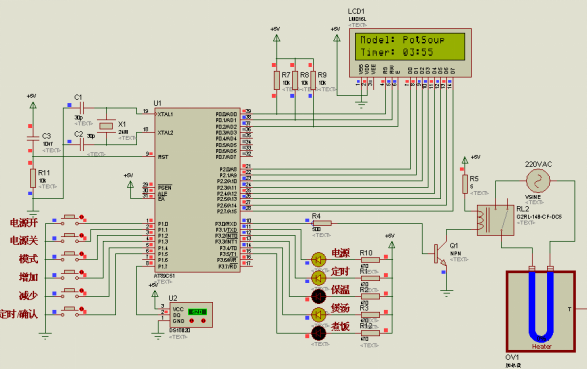
本课题以AT89C51单片机为核心器件,设计了智能电饭煲控制系统,并在PROTEUS环境中对设计进行了仿真验证。
首先,对电饭煲的发展状况进行了阐述,分析了电饭煲的发展趋势,以及智能电饭煲的发展优势。在此基础上,对智能电饭煲控制系统整体设计方案进行了论证,并确定了本课题智能电饭煲控制系统整体设计方案。
其次,从实用性、智能化、节约成本、环保节能等角度出发,对智能电饭煲控制系统的硬件、软件进行了详细设计。按照实现功能对硬件、软件进行了功能划分,并对各部分的原理、实现方法进行了详细说明。
最后,在PROTEUS仿真环境中对该设计进行了仿真验证。仿真结果表明,基于单片机的智能电饭煲控制系统整体设计方案的可行性,软件和硬件设计的正确性,整体效果较为满意。
关键词:智能控制,电饭煲,单片机,Proteus
Abstract
AT89C51 MCU was chosen as the core, component to complete the intelligent electric cooker control system design, and validated via simulation in the PROTEUS environment is.
Firstly, the current situation of the development of electric rice cooker is addressed, and electric rice cooker development trend, and the development advantage of intelligent electric cooker are analyzed. On this basis, the intelligent electric cooker control system overall design scheme is discussed, and confirmed this topic intelligent electric cooker control system overall design scheme confirmed.
Secondly, in view of practice, intelligence, cost saving, environmental protection and energy conservation, the detailed design of the intelligent electric cooker control system hardware and software were given. According to the functions, hardware and software of the system was divided, and principle, realization method was described in detail.
Finally, in the PROTEUS simulation environment the design was verified by simulation. The simulation results show that the intelligent control scheme based on single chip microcomputer for the electric cooker is feasible, software and hardware design is correct, and the overall performance is satisfactory.
Key words: Intelligent control; Electric cooker; Single chip microcomputer; Proteus
目 录
摘要 I
Abstract II
第一章 绪论 1
1.1 背景及发展 1
1.2 课题任务及意义 1
第二章 智能电饭煲控制系统整体设计方案 2
2.1 智能电饭煲控制系统简介 2
2.2 智能电饭煲控制系统电路组成 3
2.3 本章小结 3
第三章 智能电饭煲控制系统硬件设计 4
3.1 控制系统单片机最小系统工作电路 4
3.1.1 AT89C51单片机的引脚及其排列 4
3.1.2 AT89C51单片机时钟电路 6
3.1.3 AT89C51单片机复位电路 7
3.1.4控制系统单片机最小系统电路设计 8
3.2 控制系统电源电路 9
3.2.1稳压器件78L05简介 9
3.2.2电源电路设计 11
3.3 按键输入电路 11
3.3.1按键分类 11
3.3.2按键结构与特点 11
3.3.3 按键输入电路设计 12
3.4 温度传感器电路 13
3.4.1 DS18B20简介 13
3.4.2 DS18B20的使用方法 14
3.4.3温度传感器电路设计 16
3.5 LED状态指示电路 16
3.5.1 LED简介 16
3.5.2 状态指示电路设计 17
3.6 LCD显示电路 17
3.6.1 LCD-1602简介 18
3.6.2 LCD显示电路设计 18
3.7电饭锅加热电路 19
3.8本章小结 20
第四章 智能电饭煲控制系统软件设计 21
4.1软件整体结构设计 21
4.2子程序设计 22
4.2.1系统工作模式控制流程 22
4.2.2 定时功能控制流程 23
4.2.3 加热功能控制流程 25
4.3本章小结 26
第五章 智能电饭煲控制系统的仿真验证 27
5.1本章小结 30
结束语 31
致 谢 32
参考文献 33
附 录 34
附录1:智能电饭煲控制系统电路原理图 34
附录2:智能电饭煲控制系统软件源程序清单 35


