Performance of ice storage system utilizing a combined partial and full storage strategy
Abstract
A combined system is a new thermal storage strategy adopted in this study with which the two other known strategies namely, partial and full load, are compared. The results revealed that the combined system requires larger equipment size than that required by partial system to satisfy the same cooling load. Factors F and F that p f may be multiplied by the daily average cooling load to determine the optimum chillers size for a combined system are found. These factors are applicable for any cooling load and are based on a given chiller condensing and evaporating condition as used in this study. These factors are found to vary with the number of on-peak hours. Combined strategy required chiller size was found to decrease with decrease in on-peak period, hence the optimum chiller size for this new strategy was found to occur at zero on-peak hours, and i.e., when the combined system starts to operate as a partial strategy system.
Keywords: Ice storage system
1. Introduction
Thermal storage is the temporary storage of high or low temperature energy for later use. Airconditioning system that employs thermal stor-age equipment incorporates two strategies, the partial and full load. For either of these strategies, investigations were made to determine thepossible saving in chiller size as compared with conventional cooling system. The partial andfull storage strategies were previously studied independently and the results obtained had shown that the chiller size required in partial strategy is smaller than that required in full strategy to satisfy the same cooling load.
In this study a new strategy is adopted and investigated for chiller size determination. This strategy is named as a combined strategy system which includes both, the partial and full load,operating simultaneously. Hence, two sets of chillers are used in this new system, the first set operates continuously as a partial system and thesecond set operates during the off-peak period as a full system helping the first set chillers to meet the cooling load and charge the thermal storage reservoirs.
The aim of this study is to find the optimum chiller size in a combined strategy system and to compare it with that of partial strategy at different on-peak hours to meet the same cooling load. Also, a relation between the optimum chiller size and cooling load is to be determined for general use at a set of governing conditions.
To illustrate the combined strategy merits,three different case buildings with different cooling loads are investigated.
2. Theory
2.1. Assumptions
In this study, the following assumptions havebeen considered:
1) Air-cooled chillers with reciprocating compressors.
2) Evaporating pressure and temperature areconstants.
3) Refrigerant leaving the condenser and entering the expansion valve is saturated liquid.
4) Vapor leaving the evaporator and entering the compressor is saturated.
5) Refrigerant R-22 is used.
2.2. Conventional cooling system chiller
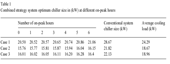
In order to show the merits of a thermal storage system, the conventional system chillers capacity has to be determined for comparison.In common practice the size of these chillers is selected equal to the maximum cooling load which happens to be 28.67, 21.82 and 22.13 KW for cases (1), (2) and (3) respectively.
2.3. Combined strategy system
In a combined system where two sets of chillers operate in partial and full strategies atthe same time, it is important to find the minimum combination chiller size that will satisfy the cooling load at a set of conditions. These conditions are the evaporating and condensing pressure and temperature and the number of on-peak hours during which only the partial chiller is kept running. The procedure adopted in this study in finding the minimum chiller size may be summarized as follow:
(a) An initial assumption of the partial chiller size is to be made. The chiller size thus assumed should be related, some how, to the cooling load.Two distinct values of the cooling load are the maximum and the average value and the later is chosen in this study. Hence the initial partial chiller size will be the average cooling load multiplied by a certain, arbitrarily selected, factor (Fp ).
(b) Since air-cooled chiller is used, its condensing temperature would vary according to inlet ambient air temperature. Therefore the initial partial chiller size would be based on the condensing temperature at which maximum cooling load occurs.
(c) Chiller capacity is then determined hourly and for the daily cycle at the different existing condensing temperature.
(d) The difference between the daily cycle cooling load and the daily total partial strategy chiller capacity would be met by the full strategy chiller. The size of this chiller is assumed to be equal to the average cooling load multiplied by a factor (F) and must equal to the difference indicated above. If this condition is not satisfied then another value of (Ff) is selected.
(e) The combined strategy chiller size obtained by the initial run with the assumed (Fp) and calculated (Ff) may not be the optimum.Therefore an iteration procedure is adopted and the factor (Fp) is changed progressively until a minimum chiller size is obtained.
(f) In order to find the relation between optimum chiller size and cooling load at different on-peak hours, the above procedure is repeated for each on-peak period (starting from six and endingwith zero on-peak). For each on-peak period an optimum chiller size is to be determined.
2.4. Calculation procedure
To start the calculation procedure, the size of the partial strategy chiller should be defined first. It shall be assumed that the size (Q sp) equal to the average cooling load (q av) for any of
the three cases multiplied by an arbitrarily
selected factor (Fp).
Qsp=q av .Fp (KWh) (1)
Ref. [1] reported that rating of air cooling condenser is based on the temperature difference between dry bulb temperature of the air entering to the coil and the condensing temperature corresponding to the pressure at inlet. The air temperature inlet to the coil is typical of Baghdad area at the 21st of July.
Ref. [2] stated that the evaporating temperature of a refrigeration system used for ice storoage, ranges between –4 and –12 C. In this study–8°C is used. Thus Qsp calculated by Eq. (1) shall be based on the maximum condensing temperature occurring during the daily cycle. Accordingly and with evaporating temperature indicated above, the partial chiller compressor displacement (V) is determined

where ηmnis the minimum volumetric efficiency of the reciprocating compressor occurring at the highest compression ratio. Ref. [3] had reported the volumetric efficiencies against different compression ratios for modern high speed refrigerant 12 and 22 compressors.
The hourly chiller capacity may then be calculated by

and accordingly the total daily capacity may be determined by summing the hourly capacity calculated by Eq. (3)

If the daily cycle total cooling load is obtained by adding up the hourly existing cooling load as given by

then the cooling load which shall be removed by the full load strategy chiller (QfT ) is simply the difference between the total daily cooling load defined by Eq. (5) and the total heat removed by the partial strategy chillers as presented by Eq. (4).

Now the size of the full strategy chiller is to be determined using the same above outlined procedure. The procedure, again, shall be started by defining the full strategy chiller size. This may be accomplished by assuming that this chiller size (Q sf), based on the maximum condensing temperature, is equal to the average cooling load(qav ) multiplied by arbitrarily factor called (Ff).

The full strategy compressor displacement (V) can now be estimated by

And the hourly chiller capacity is

Accordingly, the total capacity of the chiller when operating during the off-peak period onlywould be the sum of the hourly chiller capacity as calculated by Eq. (9)

where n1 and n2 represent the start and end of the off-peak period during which the full strategy chiller is operated.
The results obtained by Eq. (10) must equal to that given by Eq. (6) otherwise another (Ff) factor is selected and the calculation steps from Eq. (7) through Eq. (10) is repeated. Once this condition is satisfied the combined strategy chiller size would be the sum of the partial and full strategy chillers and may be expressed by

It is to be understood at this stage that for a given on-peak period and for the initial selection of (Fp ) factor as used in Eq. (1), the combined strategy chiller size expressed by Eqs. (11) and (12) may not represent the optimum size. Hence an iteration technique, by which (Fp ) factor is progressively changed in Eq. (1), is adopted. With each new value of (Fp ) the whole calculation procedure from Eq. (1) through equation (12), is repeated. The iteration process continues until the combined system chiller size is minimum.


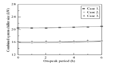
Fig. 1. Variation of the optimum chiller size for the combined system with on-peak period.
The percent reduction in combined system chiller size as compared to the conventional system chiller size to satisfy the same cooling load may be determined by

When the above calculations and iterations are completed for a certain on-peak period, then another on-peak is used and the whole procedure is repeated all over again.
3. Results and discussion
The optimum chiller size required in a combined system when applied to the three case

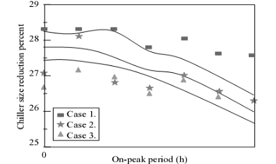
Fig. 2. Variation of the chiller size reduction percent combined system with on-peak period. buildings under study, as calculated by Eq. (11),are listed in Table 1 and plotted in Fig. 1. The illustrations show the variation in the optimum chiller size when varying the number of on-peak hours from six to zero. The conventional system chiller size required for the three case buildings and the corresponding average cooling loads are also included in the same table for comparison.
The results show that the combined system optimum chilled size decreases, as the numbers of on-peak hours are less. The minimum chiller size that would satisfy the cooling load is found to take place when the number of on-peak hours approaches zero. The zero on-peak hours indicates that only partial strategy chiller is in operation during the whole daily cycle.
The percent reductions in chiller size when combined system is used at each on-peak period as compared to the conventional system chiller size are shown in Fig. 2. The figure clearly shows that the highest percent reduction achievement in chiller size is at zero on-peak hours. Also the figure indicates that percent reductions for all the cases are almost the same.
The value of the factors F pand Ft at different on-peak hours are listed in Table 2. These values when multiplied by the average cooling load will yield the minimum combined system chiller size at a given on-peak hour. This is presented Table 2 Partial and full strategy system factors at different on-peak hours

by Eq. (12). Any alteration in these factors will result in over estimated combined system chiller size. It is of interest to note that for the three different cases cooling loads the same values of Fp and Ff were found to appear for each on-peak period. From these results it may be concluded that these factors may be applied with any other cooling load to find the required minimum chiller size. This is true as long as the conditions are the same as those assumed in this study.
4. Conclusions
1) Combined strategy system requires less chiller size than conventional system does. A reduction of about 28% may be achieved.
2) Partial chiller strategy requires less chiller size than combined system.
3) Combined strategy chiller size was found to decrease with decrease in on-peak period.
4) Factors Fp and Ff found in this study can be used with any other cooling load to estimate the minimum required chiller size.
Nomenclature
F factor
H refrigerant enthalpy KJ/kg
Q chiller capacity KW
qt hourly cooling load KW
V refrigerant volume flow rate (m /s)
Subscript
Av average
Com combined
conv conventional
f full storage
mn minimum
p partial chiller
sf size of full strategy chiller
sp size of partial strategy chiller
Tp total chiller capacity for partial strate
total
time
inlet to compressor state
outlet from e×pansion valve state


