Sand Filters
DESCRIPTION
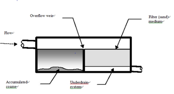
Sand filters comprise a bed of sand (or other medium) through which runoff is passed.
The filtered runoff is collected by an underdrain system
.
SELECTION CRITERIA/ADVANTAGES
• Principal objective is the retention of particulates.
• Can be appropriate in areas where runoff is insufficient or too unreliable, evaporation
rates are too high or soils are too pervious to sustain the use of constructed wetlands.
• Appropriate for retrofitting, sites with space limitations and underground installation.
• Generally suitable for stabilised and largely impervious catchments up to 25 ha.
POLLUTANT TRAPPING EFFICIENCY
|
LITTER
|
L
|
SADIMANT
|
M
|
NUTRIANTS
|
M
|
|
OXYGEN DEMANDING MATTERIAL
|
M
|
OIL AND GRESSE
|
M
|
BACTERIA
|
H
|
LIMITATIONS/DISADVANTAGES
Limited removal of dissolved pollutants (e.g. dissolved nutrients).
Upstream litter and coarse sediment removal is required to minimise clogging.
Easily clogged, and effectiveness is highly dependent upon frequent maintenance.
High head loss and relatively low flow rates through the filter.
Large sand filters without grass cover can be unattractive in residential areas.
COST CONSIDERATIONS
Moderate to high capital cost, moderate to high maintenance costs.
ADDITIONAL INFORMATION
Sand filters are a form of infiltration system often constructed within a formal tank. The
filter medium (commonly sand, although peat, limestone and topsoil have been used)
overlies an underdrain system. Runoff is diverted on to the filter medium, where it ponds
and flows through the medium, and is collected in the underdrain and discharged. It is a
variation on the sand filters used for water treatment purposes.
Sand filters are provided with an upstream pre-treatment system to remove coarse
sediment and to distribute the inflow evenly across the sand filter. The pre-treatment
system (sedimentation) is generally intended to trap sand and gravel while the filter can
remove finer silt and clay particles.
There are two broad scales of sand filters:
• large sand filters suitable for catchments of up to 25�C50 ha, which include a pre-treatment basin for settling. These filters can have topsoil and grass cover. They can treat flow from floodways or piped systems.
• small sand filters in underground pits/chambers generally applicable for highly impervious catchments of up to 2 ha. They are usually installed within the piped drainage system.
Pollutant removal processes are sedimentation within the filter (or the upstream pre-treatment facility) and infiltration through the filter media. This removes finer particulate material and any associated pollutants.
The actual performance of a sand filter will depend on the characteristics of the inflow sediments (e.g. grading), which can relate to catchment geology and soil type. For example, clay soils might require a greater filter size, although the influence of soil type can be expected to decrease with catchment impervious fraction (ARC 1992).
Care should be taken with the installation/operation of a sand filter if the upstream catchment is generating considerable sediment loads (i.e. construction activities or erosive pervious areas). These sediment loads can clog the filter, resulting in the need to replace
the filter media.
The performance monitoring of sand filters has been relatively limited, although the results to date (summarised in Table 5.3) indicate comparatively high removal rates for most pollutants (with the notable exception of oxidised nitrogen). Overall, removal rates are similar to those for constructed wetlands.
Table 5.3 �C Pollutant Retention Rates for Sand Filters
|
POLLUTANT
|
RETENTION(��)
|
POLLUTANT
|
RETENTION(��)
|
|
SUSEPENDED SOLIDS
|
60-90
|
TOTAL PHOSPHORUS
|
35-80
|
|
TOTAL ROGENNIT
|
40-70
|
OXIDISED NITROGEN
|
-110-0
|
|
LEAD
|
65-90
|
BIOCHEMICAL OXYGEN DEMAND
|
60-80
|
|
ZINC
|
10-80
|
CHEMICAL OXYGEN DEMAND
|
35-70
|
KEY PERFORMANCE FACTORS
Pre-treatment to remove coarse sediment and other debris (to minimise clogging of the
filter).
Appropriate filtration period.
Uniform flow across filter.
DESIGN CONSIDERATIONS
Large sand filters
Sizing
There are two components to be sized for large sand filters, namely the upstream settling (or pre-treatment) basin and the filter. These components can be designed on the basis of a design storm event and high flows in excess of the design storm can be designed to bypass the filter.
The upstream settling basin should be designed for a removal efficiency that avoids rapid clogging of the filter. The approach suggested by CDM (1993) is an extended detention basin based on a water quality design storm that achieves 60-75% of the suspended solids retention objective and a drawdown time of 24 hours. A perforated riser pipe can be used as the outlet for the basin, as described in Section 5.3 (Extended Detention Basins).
ARC (1992) recommend a settling basin with a permanent pool. This pool could be sized to achieve the same retention as the extended detention settling basin, using settling velocity theory or the retention curves contained in Section 6.1 (Constructed Wetlands).Alternatively, the pool could be sized as for a sediment trap, described in Section 4.3.
A decision on whether an extended detention or permanent pool should be adopted could be based on whether local climatic conditions enable a permanent pool to be sustained. A permanent pool system is likely to result in a smaller volume than an extended detention system for the same sediment retention. However, sediment removal might be easier for an
extended detention system, which would drain between storm events.
The surface area of the filter can be derived from the following equation (after ARC 1992):
A = VD/Kt��h+d��
Where A = suface area of filter (m )
V = Volume to be infiltrated (m )
K = hydraulic conductivity (m/h)
T = drainage time
H = average head above filter [half the storage depth] (m)
D = depth of filter (m)
ARC (1992) recommends a hydraulic conductivity of 0.033 m/h, which corresponds to asystem with partial and full pre-treatment (City of Austin 1988). This is less than thetypical conductivity of new sand media and hence accounts for some clogging. ARC (1992) recommends a minimum media depth of 0.4 m. A filtration time of 24 hours isrecommended by CDM (1993) and City of Austin (1988), while ARC (1992) recommend a 16 hour period, corresponding to one-third of the mean inter-event period. This criterion was adopted so that the filter has a dry period between events to maintain aerobic conditions and hence long term infiltration capability. The filtration period could therefore be based on rainfall patterns at the proposed site, based on the underlying criteria adopted by ARC (1992).
Geometry
Other characteristics of the settling basin that can enhance efficiency include (CDM 1993;
City of Austin, 1988; ARC 1992):
• energy dissipation at the inlet
• flow velocities to minimise re-suspension (e.g. <0.3 m/s)
• effective use of the storage volume (i.e. minimising short circuiting). A length to width
ratio of at least 3:1 to 5:1 could be adopted.
• access for maintenance for sediment removal
• litter rack at the outlet from the settling basin.
Characteristics of the filter that optimise efficiency include (CDM 1993; City of Austin,
1988; ARC 1992):
• use of a flow spreader to achieve a uniform flow distribution over the filter. A saw-tooth weir could be used for this purpose.
• a geotextile fabric over a coarse gravel layer above the under-drain.
CDM (1993) adopt a sand size of between 0.5 and 1.0 mm, and the City of Austin (1988)
adopt 0.25 to 0.5 mm. ARC (1992) recommends 10% should pass a 63 µm sieve and 90 should pass a 500 µm sieve.
A peat�Csand media has been proposed by Galli (1991), where the peat has an enhanced adsorption capacity to remove dissolved pollutants. Other types of organic media could be used, although the hydraulic conductivity might be lower, requiring an larger filter.
Small sand filters
The upstream sedimentation chamber and the filter also need to be sized for small sand filters. These components can be designed on the basis of a design storm event and high flows in excess of the design storm can be designed to bypass the filter. The sedimentation chamber can be designed using the sediment trap sizing technique (section 4.3), and the filter designed using the technique noted above. Shaver (1996) presents an example of a small sand filter design.
INSPECTION/MONITORING
Sand filters can be monitored on a regular basis and after every large storm event for:
• ponding, clogging and blockage of the filter media
• depth of sediment in the settling tank/sedimentation chamber
• blockage of the outlet from the settling tank/sedimentation chamber to the filter.
MAINTENANCE
The following maintenance activities might be required for sand filters:
• The sediment and litter should be removed from the settling basin/sedimentation chamber, with drying of the sediment possibly required before disposal.
• The filter surface could be regularly raked to remove sediment and to break up any crusts (to improve infiltration).
• The top layer (50�C100 mm) of the filter media can be removed and replaced.
• If the filter is not cleaned frequently, the entire filter media might need to be replaced due to migration of sands within the media. This can result in frequent maintenance
being more cost-effective in the long term.
• Contaminated sand and other material removed from the filter or the sedimentation chamber (if applicable) can be removed to landfill.
ADDITIONAL REFERENCES
Shaver (1996), CDM (1993), Truong and Phua (1995), Horner et al (1994), Schueler
(1987), Schueler et al (1992), OMEE (1994), Galli (1992).
