Visualization of PLC Programs using XML
M. Bani Younis and G. Frey
Abstract - Due to the growing complexity of PLC programs there is an increasing interest in the application of formal methods in this area. Formal methods allow rigid proving of system properties in verification and validation. One way to apply formal methods is to utilize a formal design approach in PLC programming. However, for existing software that has to be optimized, changed, or ported to new systems .There is the need for an approach that can start from a given PLC program. Therefore, formalization of PLC programs is a topic of current research. The paper outlines a re-engineering approach based on the formalization of PLC programs. The transformation into a vendor independent format and the visualization of the structure of PLC programs is identified as an important intermediate step in this process. It is shown how XML and corresponding technologies can be used for the formalization and visualization of an existing PLC program.
I. INTRODUCTION
Programmable Logic Controllers (PLCs) are a special type of computers that are used in industrial and safety critical applications. The purpose of a PLC is to control a particular process, or a collection of processes, by producing electrical control signals in response to electrical process- related inputs signals. The systems controlled by PLCs vary tremendously, with applications in manufacturing, chemical process control, machining, transportation, power distribution, and many other fields. Automation applications can range in complexity from a simple panel to operate the lights and motorized window shades in a conference room to completely automated manufacturing lines.
With the widening of their application horizon, PLC programs are being subject to increased complexity and high quality demands especially for safety-critical applications. The growing complexity of the applications within the compliance of limited development time as well as the reusability of existing software or PLC modules requires a formal approach to be developed. Ensuring the high quality demands requires verification and validation procedures as well as analysis and simulation of existing systems to be carried out. One of the important fields for the formalization of PLC programs that have been growing up in recent time is Reverse-engineering . Reverse Engineering is a process of evaluating something to understand how it works in order to duplicate or enhance it. While the reuse of PLC codes is being established as a tool for combating the complexity of PLC programs, Reverse Engineering is supposed to receive increased importance in the coming years especially if exiting hardware has to be replaced by new hardware with different programming environments
Visualization of existing PLC programs is an important intermediate step of Reverse Engineering. The paper provides an approach towards the visualization of PLC programs using XML which is an important approach for the orientation and better understanding for engineers working with PLC programs.
The paper is structured as follows. First, a short introduction to PLCs and the corresponding programming techniques according to the IEC 61131-3 standard is given. In Section Ⅲ an approach for Re-engineering based on formalization of PLC programs is introduced. The transformation of the PLC code into a vendor independent format is identified as an important first step in this process. XML and corresponding technologies such as XSL and XSLT that can be used in this transformation are presented in Section IV. Section V presents the application of XML for the visualization of PLC programs and illustrates the approach with an example. The final Section summarizes the results and gives an outlook on future work in this ongoing project.
Ⅱ PLC AND IEC 61131
Since its inception in the early 70s the PLC received increasing attention due to its success in fulfilling the objective of replacing hard-wired control equipments at machines. Eventually it grew up as a distinct field of application, research and development, mainly for Control Engineering.
IEC 61131 is the first real endeavour to standardize PLC programming languages for industrial automation. In I993 the International Electrotechnical Commission published the IEC 61131 Intemational Standard for Programmable Controllers. Before the standardization PLC programming languages were being developed as proprietary programming languages usable to PLCs of a special vendor. But in order to enhance compatibility, openness and interoperability among different products as well as to promote the development of tools and methodologies with respect to a fixed set of notations the IEC 61131 standard evolved. The third part of this standard defines a suit of five programming languages:
Instruction List (IL) is a low-level textual language with a structure similar to assembler. Originated in Europe IL is considered to be the PLC language in which all other IEC61131-3 languages can be translated.
Ladder Diagram (LO) is a graphical language that has its roots in the USA. LDs conform to a programming style borrowed from electronic and electrical circuits for implementing control logics.
Structured Text (STJ) is a very powerful high-level language. ST borrows its syntax from Pascal, augmenting it with some features from Ada. ST contains all the essential elements of a modem programming language.
Function Block Diagram (FBD) is a graphical language and it is very common to the process industry. In this language controllers are modelled as signal and data flows through function blocks. FBD transforms textual programming into connecting function blocks and thus improves modularity and software reuse.
Sequential Function Chart (SFC) is a graphical language. SFC elements are defined for structuring the organization of programmable controller programs.
One problem with IEC 61131-3 is that there is no standardized format for the project information in a PLC programming tool. At the moment there are only vendor specific formats. This is also one reason for the restriction of formalization approaches to single programs or algorithms. However, recently the PLC users’ organization PLCopen started a Technical Committee to define an XML based format for projects according to IEC 61131-3. This new format will ease the access of formalization tools to all relevant information of a PLC project.
Ⅲ. RE-ENGINEERING APPROACH
The presented approach towards re-engineering (cf. Fig.1) is based upon the conception that XML can be used as a medium in which PLC codes will be transformed.
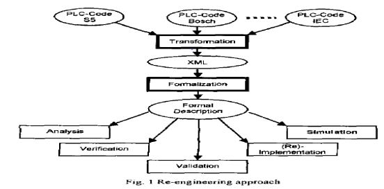
This transformation offers the advantage of obtaining avendor independent specification code. (Even if the PLCopen succeeds in defining a standardized format for PLC applications, there will remain a lot of existing programs that do not conform to this standard.)
Based on this code a step-wise transformation to a formal model (automata) is planned. This model can then be used for analysis, simulation, formal verification and validation, and finally for the re-implementation of the optimized algorithm on the same or another PLC.
Since re-engineering of complete programs will, in most cases, be only a semi-automatic process, intermediate visualization of the code is an important point. At different stages of the process different aspects of the code and/or formal model have to be visualized in a way that a designer can guide the further work. XML with its powerful visualization and transformation tools is an ideal tool for solving this task.
IV. XML AS A TOOL FOR VISUALIZATION
XML (extensible Markup Language) is a simple and flexible meta-language, i.e, a language for describing other languages. Tailored by the World Wide Web Consortium (W3C) as a dialect of SGML [S], XML removes two constraints which were holding back Web developments. The dependence on a single, inflexible document type (HTML) which was being much abused for tasks it was never designed for on one side; and the complexity of full SGML, whose syntax allows many powerful but hard-to-program options on the other side.
While HTML describes how data should be presented, XML describes the data itself. A number of industries and scientific disciplines-medical records and newspaper publishing among them-are already using XML to exchange information across platforms and applications. XML can be tailored to describe virtually any kind of information in a form that the recipient of the information can use in a variety of ways. It is specifically designed to support information exchange between systems that use fundamentally different forms of data representation, as for example between CAD and scheduling applications.
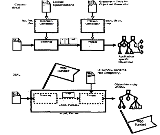
 Using XML with its powerful parsers and inherent robustness in terms of syntactic and semantic grammar is more advantageous than the conventional method of using a lexical analyzer and a
Fig2 Comparison of the resolver to use
validating parser.
The conventional method of analysis of program code requires a scanner (lexical analyser) which generates a set of terminal symbols (tokens) followed by a parser that
checks the grammatical structure of the code and generates an object net. In the object net the internal structure of the program is represented by identified objects and the relations between them. Both the scanner and the parser to be used in this method are document oriented which implies that analysis of different types of documents requires rewriting the generated code for the scanner and the parser. An example of an application of this method can be found in .
The most promising aspect of using XML instead is that XML and its complementary applications for transformations are standardized so as to provide maximum flexibility to its user.
The XML based method is advantageous, since the lexical specification is an invariant component of XML; therefore the well-formedness is independent from the respective individual application.
Hence, an XML-Parser also can transfer well-shaped XML documents in an abstract representation called Document Object Model (DOM) without using a grammar. DOM is an application programming interface (APII) for valid HTML and well-formed XML documents. It defines the logical structure of documents and the way a document is accessed and manipulated. In the DOM specification, the term "document" is used in a broad sense increasingly. XML is used as a way of representing many different kind of information that may be stored in diverse systems, and much of this would traditionally be seen as data rather than as documents. Nevertheless, XML presents this data as documents, and the DOM can be used to manage this data[5].
XSLT, the transformation language for XML is capable of transforming XML not only to another XML or HTML but to many other user-friendly formats. Before the advent of XSLT, the transformation of XML to any other format was only possible through custom applications developed in a procedural language such as C++, Visual Basic or, Java. This procedure lacked the generality with respect to the structural variation of XML documents. Capitalizing on the concept that the custom applications for the transformations are all very similar, XSLT evolved as a high-level declarative language [9].
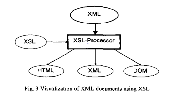 XSLT functions in two steps. In the first step, it performs a structural transformation so as to convert the XML into a structure that reflects the desired output. The second stage is formatting the new structure into the required format, such as HTML or PDF (cf. Fig. 3 ). The most important advantage of this transformation is that it allows a simple and easily-conceivable representation of the document or data structure embedded inside the well-structured but hard-to-understand XML to be produced. When HTML is chosen as the format of the transformed produce it is possible to use the extensive ability of HTML to produce an easily-conceivable and attractive visualization of a program.
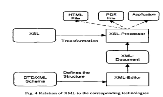
Every XML document has its own syntax and vocabulary. Therefore, in addition to being well-formed, the XML document needs to conform to a set of rules. According to W3C recommendations this set of rules has to be defined either through a Document Type Definition (DTD) or an XML Schema. The rules defined in a DTD or an XML Schema state the hierarchical and structural constraints of the XML document.
The DTD is for defining the document grammars; more recently a number of alternative languages have been proposed. The W3C XML Schema language replicates the essential functionality of DTDs, and adds a number of features: the use of XML instance syntax rather than an ad hoc notation, clear relationships between schemas and namespaces, a systematic distinction between element types and data types, and a single-inheritance form of type derivation. In other words schemas offer a richer and more powerful way of describing information than what is possible with DTDs. Fig. 4 shows the XML technologies discussed above and the connection between them.
V. AN APPROACH FOR THE VISUALIZATION OFPLC PROGRAMS
A. Overview
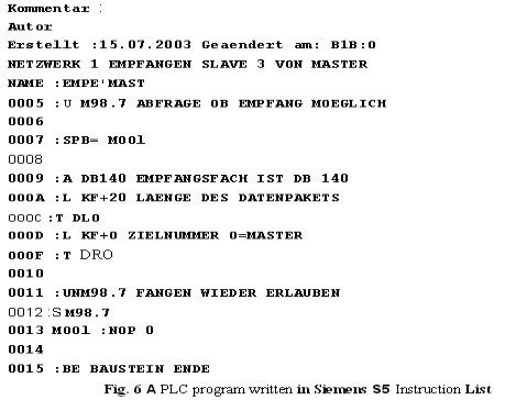
 Since Instruction List (IL) is the most commonly used PLC language in Europe, the presented approach is based on this language. The proprietary IL dialect Siemens STEP 5 and the standardized version according to IEC 61131-3 are considered.
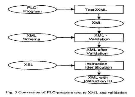
The generation of XML documents showing different aspects of a PLC program is realized in the following three steps:
1.Transformation of the PLC program to an XML document
2.Validation of the XML against the XML Schema which sets the syntax of the XML
3.Identification of the Instruction elements of the transformed XML according to the instruction set of the source PLC
These three steps are discussed in sub-sections B to D respectively. Sub-section E explains the visualization of the different XMLs obtained during the preceding steps.
Throughout this Section an example is used to illustrate the presented concepts. Fig. 6 shows a PLC code written in Instruction List Siemens S5. The PLC code is written in atabular form where each row element is either a delimited list consisting of address, label, instruction, operand and description or a comment.
B. Conversion of a PLC Program inio a well-formed XML
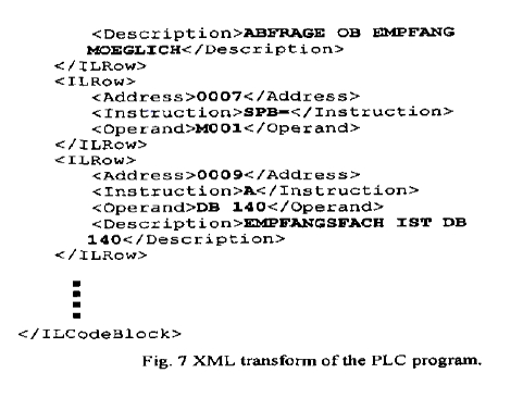
Given a PLC program in ASCII format and in a tabular structure with separate columns for addresses, labels, instructions, operands and descriptions delimited by whitespaces, XSLT can convert it into a well-formed XML document. The XML document obtained through this transformation is a hierarchically structured document.
Fig. 7 shows the XML document obtained through the transformation of the PLC code of Fig. 6. The XML document is structured in a hierarchy in which the root element is the IL Code Block representing the whole PLC code. Each of the rows of the PLC code is contained within a corresponding ILRow element which is M e r smtctured into child elements.
Note: The structure chosen for the XML representation of IL-Code is oriented at the working proposal of the PLCopen.
C. XML Validation against the XML Schema
The XML obtained as a result of the previous processing can be validated using a validating parser that confirms that the XML document in addition to being well-formed conforms to the set of syntactic rules defined in context of the PLC programming language.
D. rdenhpcation of instructions
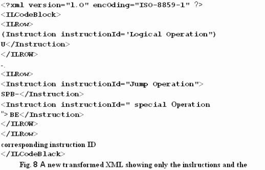
This step in the process of visualization of PLC programs using XML ensures that the XML document to be used for visualization contains only valid instructions.XSLT can be used to transform the well-formed and valid XML to another XML which as a result of identification on instructions has an additional attribute appended to the instruction tags. This attribute notifies whether the instruction is a valid instruction of the concerned instruction set. This transformation procedure is also capable of attaching attributes to the instruction tags that declares a classification of the instructions into predefined classes.
The instruction identification of the transformed XML proofs the semantic of the XML in accordance with the operation types of the PLC programming language.
In the example of this section(cf. Fig. 8), the new XML contains additional attributes which classify the instructions according to the type of operation it represents. The STEPS instructions are categorized into eleven different types of operations e.g. logical, jump, load or transfer operation assignment, etc.
E. Visualization of XML
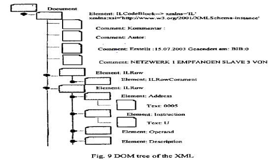
Both of the XML documents generated above can be transformed into HTML or other readable documents with the help of XSL. An ingenious XSL can be designed so as to produce an HTML which can convey the logical and other features of the PLC program in an easily conceivable form. Moreover, the DOM structure embedded in the XML (cf. Fig. 9), also enables the user to navigate through the PLC programs in an easy way.
For the example the visualization is done in HTML. This visualization is done for the transformed XML after the validation of it's syntax as a table where the child elements of the ILRow are the columns of this table.
The XML after the instruction identification is transformed using the XSL, where the instruction and the instruction Id, obtained after extracting the XML according to the type of operations are visualized in a table containing two columns (Instruction, Instruction Id) in HTML.
The HTML structures suggested here are not the only possibilities, with which the XML can be visualized, but they give a very easy practical option for the user's grasp of the PLC code.
Fig. IO shows the same PLC code as shown in Fig. 4 as a HTML document converted &om the XML document shown in Fig. 7 using XSL. This visualization
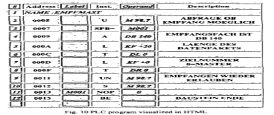 enables a better understanding of the PLC program. Fig. 11 shows the special visualization of instruction ids given in the XML of Fig. 6.
VI. CONCLUSIONS AND OUTLOOK
Re-engineering of PLC programs needs a formal approach to be developed. In this paper one way to solve this task is introduced. Based on a given PLC program written in Instruction List a step-wise transformation to a formal representation is proposed. Since this process will not be fully automatic, the need for flexible visualization of intermediate steps is derived. XML is presented as a flexible, standardized means to serve as data format for the description of the PLC code. The corresponding technology of XSL transformations and the Document Object Model are presented as tools for the variety of customized visualization tasks during the re-engineering process.
Based on the XML description of PLC programs further transformations will be applied to finally derive a completely formalized description of the original PLC code. This will be in the form of a finite automaton. During this process it is planned to identify common IL structures and formalize them via a library.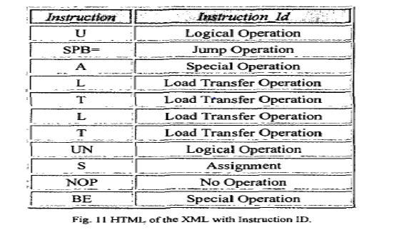 Gaining the Benefit of the XML Metadata Interchange (XMI) as an open industry standard that applies XML to abstract systems such as UML and referring to the classification of the instructions of IL into the eleven categories mentioned above. We can extract UML classes from this classification, as it resembles the action semantics of UML.
