Abstract: this paper describes the nc milling roller, the overall design and analyses the bilateralsuper-modulus gear pair of driving mechanism of the main points of design,installationguidesurface of the X axis is introduced in this paper
Keywords: mobile nc milling design
This machine is mainly used for metal parts of the plane and inclined plane work. It has enough rigidity, Milling head adopts milling head in Taiwan, Milling head with flexible, Spindle motor is frequency conversion motor. It can undertake stepless speed, Ensure accuracy of machine tools and machining precision has good stability, This machine is of high efficiency and exercise,For convenience, make the drive more reliable and convenient in maintenance, less consumption, beautiful modelling, etc, widely used in mechanical manufacturing industry.
This paper described the mobile CNC milling refers to longmen framework Vertical milling movement. The biggest advantage of milling roller is (1) Machine cover an area of an area small. Workbench mobile Longmen milling machine, complete machine must be higher than vertical stroke length two times. However, Workbench mobile Longmen milling machine, The length of side frame which is fabricated according to add only longitudinal travel width, The dynamic response of the machine is good. Workbench mobile Longmen milling machine adopts fixed table. The whole cast out with bed, Longmen framework of longitudinal motionDrive torque equivalent unchanged, It is not because of bearing the weight of the workpiece changesChange, so as to ensure the accuracy and performance of the machine tool.
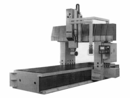
The independent design mobile nc Longmen milling(FIG 1)has been a special machine to use. It can satisfy the large castings, steel parts boring and milling, drilling, etc multiple operation process. It is right milling head, It also can process the 4 side of workpiece. The goal of the main design parameters such as Longmen milling under: workbench area 1800mm × 4000mm, The travel for X axis:4000mm The travel for Y axis:2000mm The travel forZ axis:750mm, Spindle power 18.5KW, Each axis rapid federate 10m/min.

Figure 1 Mobile nc milling
1. Mechanical parts design
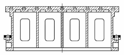
The bed include Bed, Slide, Longmen frame spindle box, Three axis to drive mechanical parts and related CNC servo part, Now ,The design process is emphasized as follows: The bed is the basic design work, The size of the bed of the design affects the complete machine design. And the rationality of the design of directly affect the whole Machine stiffness. The cross-section shape for the bed like ∏,(FIG 2) The plane is working on a bed of mesa design has 9 T shaped groove. For the convenience of bed and working mesa of pure dig imageT processing, groove tank completely, The right and left two concerning the design has a long narrow swing plane. It is used to linear rolling guide vice, The author put rail surface design in the two side bed. The main consideration of force transmission directions and unloading, Because the bed will be dragon framework of gravity, cutting force and the gravity of the workpiece, This design can directly into the gravity of longmen framework to machine tools, and Bed only suffer the gravity of the workpiece. The bed by the following basic wall thickness determine By the following formula.
C=1/4(2L+B+H)
Type: C,L,B is respectively for bed length, width and height of size and unit for the m.
Based on equivalent size c, Consulting relevant form,Take the basic wall thickness is 38mm,

Figure 2 Shape of concerning the cross-section
Spindle box adopts 300 mm × 300 mm section design. The torsion bending capacity are stronger. Spindle gearboxes USES two gears Gear sliding speed-change mechanism.
It can adapt rough machining requirements. Spindle unit adopts four supporting structure, Ahead three groups of Angle contact ball bearing used to withstand cutting force. Spindle end a deep groove ball bearings are used to unloading, That is not of the Sliding gears of the additional moment.
Longmen framework used integral frame which is fabricated according to the design concept, It took about beam and column design into a whole. Although make casting and assembly adjusting difficulty, the whole framework of longmen rigid better, more important is to slide have assembled spindle box, etc. Slide is designed in the frame which is fabricated according to the geometrical dimensions and spindle box, According to the center axis of the guide bar as far as possible to face for the principle, The Z axis and the driver installation position in design, effectively reduce the weight of the slide.
Designed to drive into the idea as follows, The X axis to drive
Use the bilateral super-modulus gear pair aggravating preloading linear rolling guide vice.X axis and Y axis uses big diameter ball screw preloading vice hardened guide. Rail sliding parts attached engineering plastics, It avoids low when crawling phenomenon, and guide the design is inclined with adjustable device. This machine design make the whole machine to coordinate performance. The axis of the feeding speed and force get the optimal matching.
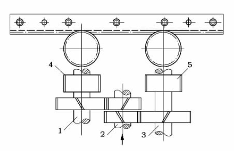
Due to the longitudinal axis machine movement X, and is moving longmen framework of longmen framework weighed 10T, so the linear rolling guide rails to must choose.Because the ball rail system of small friction coefficient, very suitable for longmen framework of moving rigidity requirement.Guide the slider choose one type, each slide block dynamic load can achieve 10t. Considering the safety coefficient, every guide installation 2 slider. Longmen framework for the driver bilateral super-modulus gear pair (see chart 2), feed movement by 3 input, through two inclined gear motor shaft/and axis to 2, and then by two gear - and to drive rack. And thus promote longmen framew3 the helical gear axle spiral of the two opposite directions. Through the spring in the shaft on a three axial force F, make the helical gear trace of axial movement produced at 1 and 2 and axial shaft in the opposite direction Angle of small, round 4 and 5) respectively, the gear tooth surface with two rack, eliminate the gap.

1.2.3--- axis 4.5--- Rack
Figure 3 Bilateral super-modulus gear pair
Spindle box and vertical motion Z axis adopts ball screw assembly transmission. Because of this machine is not high speed milling machine, the Z axis of the feeding system for servo motor through the ratio of 4 for parallel axis set than gearbox drives the ball screw rotation. In the design of special attention to the Z axis of safety problems. First choose the servo motor with electromagnetic brake, second in the ball screw with a two-way overrunning clutch, prevent ball nuts rotation caused spindle box mechanical prolapse. Of course, in order to protect the z-axis feed institutions, but also in the accuracy with two balance on the slide cylinders. Balance Q, etcThe quality of parts in spindle box 85%.
Spindle box around move for the Y axis, in order to guarantee the precision Y axis, and only by their level of ball screw and axial force, servo motor and the ball screw straight league. The author selects the coupling with overload protection device, in the overload when coupling automatically.
2 Selection of CNC system
The Siemens numerical control system is adopted, because this system 840D provides longmen shaft synchronization function. Use this function, the machine can to dragons
Door frame for shaft (into) no, X2 clamps its X1 mechanical deviation of displacement. The actual value can exercise for comparison, even the smallest deviation can be corrected, and therefore improve the accuracy of the X axis movement
3 Epilogue
The author finally, according to the professional machine parts manufacturers to provide design samples design will reach the twice the result with half the effort. In The design process, the author of CNC system, spindle unit, gearbox, super-modulus gear and ball screw guide etc. According to the sample of empirical formulas, not only shorten design time, make the higher reliability. At the same time we must pay great attention to the timely design machine tools, such as the application of three-dimensional software components immediately after the establishment sketches for 3d model, through the assembly interference, machine avoid collisions occur when in assembly Wade rework phenomenon.


