SHT1x / SHT7x
Humidity & Temperature Sensor
 - Relative humidity and temperature sensors
- Dew point
- Fully calibrated, digital output
- Excellent long-term stability
- No external components required
- Ultra low power consumption
- Surface mountable or 4-pin fully interchangeable
- Small size
- Automatic power down
SHT1x / SHT7x Product Summary
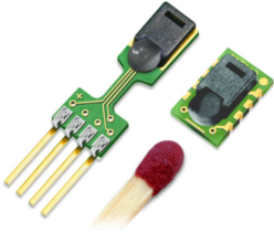
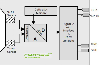
The SHTxx is a single chip relative humidity and temperature multi sensor module comprising a calibrated digital output. Application of industrial CMOS processes with
patented micro-machining (CMOSens® technology) ensures highest reliability and excellent long term stability. The device includes a capacitive polymer sensing element for relative humidity and a bandgap temperature sensor. Both are seamlessly coupled to a 14bit analog to digital converter and a serial interface circuit on the same chip. This results in superior signal quality, a fast response time and insensitivity to external disturbances (EMC) at a very competitive price.Each SHTxx is individually calibrated in a precision humidity chamber with a chilled mirror hygrometer as reference. The calibration coefficients are programmed into the OTP memory. These coefficients are used internally during measurements to calibrate the signals from the sensors. The 2-wire serial interface and internal voltage regulation allows easy and fast system integration. Its tiny size and low power consumption makes it the ultimate choice for even the most demanding applications.The device is supplied in eith surface-mountable LCC (Leadless Chip Carrier) or as a pluggable 4-pin single-in-line type package. Customer specific packaging options may beavailable on request.
Applications
_ HVAC
_ Automotive
_ Consumer Goods
 _ Weather Stations
_ Humidifiers
_ Dehumidifiers
_ Test & Measurement
_ Data Logging
_ Automation
_ White Goods
_ Medical
2 Interface Specifications
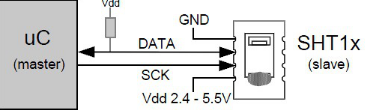
Figure 2 Typical application circuit
2.1 Power Pins
The SHTxx requires a voltage supply between 2.4 and 5.5 V. After powerup the device needs 11ms to reach its “sleep” state. No commands should be sent before that time.Power supply pins (VDD, GND) may be decoupled with a 100 nF capacitor.
2.2 Serial Interface (Bidirectional 2-wire)
The serial interface of the SHTxx is optimized for sensor readout and power consumption and is not compatible with I2C interfaces, see FAQ for details.
2.2.1 Serial clock input (SCK)
The SCK is used to synchronize the communication between a microcontroller and the SHTxx. Since the interface consists of fully static logic there is no minimum SCK
frequency.
2.2.2 Serial data (DATA)
The DATA tristate pin is used to transfer data in and out of the device. DATA changes after the falling edge and is valid on the rising edge of the serial clock SCK. During transmission the DATA line must remain stable while SCK is high. To avoid signal contention the microcontroller should only drive DATA low. An external pull-up resistor (e.g. 10 kΩ ) is required to pull the signal high. (See Figure 2) Pull-up resistors are often included in I/O circuits of microcontrollers. See Table 5 for detailed IO characteristics.
2.2.3 Sending a command
To initiate a transmission, a “Transmission Start” sequence has to be issued. It consists of a lowering of the DATA line while SCK is high, followed by a low pulse on SCK and raising DATA again while SCK is still high.

Figure 3 "Transmission Start" sequence
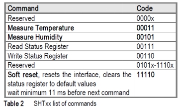
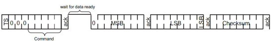
The subsequent command consists of three address bits (only “000” is currently supported) and five command bits. The SHTxx indicates the proper reception of a command by pulling the DATA pin low (ACK bit) after the falling edge of the 8th SCK clock. The DATA line is released (and goes high) after the falling edge of the 9th SCK clock.
2.2.4 Measurement sequence (RH and T)
After issuing a measurement command (‘00000101’ for RH, ‘00000011’ for Temperature) the controller has to wait for the measurement to complete. This takes approximately 11/55/210 ms for a 8/12/14bit measurement. The exact time varies by up to ±15% with the speed of the internal oscillator. To signal the completion of a measurement, the SHTxx pulls down the data line and enters idle mode. The controller must wait for this “data ready” signal before restarting SCK to readout the data. Measurement data is stored until readout, therefore the controller can continue with other tasks and readout as convenient.
Two bytes of measurement data and one byte of CRC checksum will then be transmitted. The uC must acknowledge each byte by pulling the DATA line low. All
values are MSB first, right justified. (e.g. the 5th SCK is MSB for a 12bit value, for a 8bit result the first byte is not used). Communication terminates after the acknowledge bit of the CRC data. If CRC-8 checksum is not used the controller may terminate the communication after the measurement dat LSB by keeping ack high. The device automatically returns to sleep mode after the measurement and communication have ended. Warning: To keep self heating below 0.1 °C the SHTxx should not be active for more than 10% of the time (e.g. max. 2 measurements / second for 12bit accuracy).
2.2.5 Connection reset sequence
If communication with the device is lost the following signal sequence will reset its serial interface:
While leaving DATA high, toggle SCK 9 or more times. This must be followed by a “Transmission Start” sequence preceding the next command. This sequence resets the
interface only. The status register preserves its content.
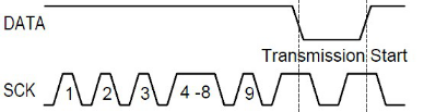
Figure 4 Connection reset sequence
2.2.6 CRC-8 Checksum calculation
The whole digital transmission is secured by a 8 bit checksum. It ensures that any wrong data can be detected and eliminated.
Please consult application note “CRC-8 Checksum Calculation” for information on how to calculate the CRC.

2.3 Status Register
Some of the advanced functions of the SHTxx are available through the status register. The following section gives a brief overview of these features. A more detailed description is available in the application note “Status Register

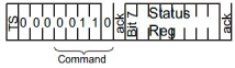
Figure 7 Status Register Write Figure 8 Status Register Read
2.3.1 Measurement resolution
The default measurement resolution of 14bit (temperature) and 12bit (humidity) can be reduced to 12 and 8bit. This is especially useful in high speed or extreme low power
applications.
2.3.2 End of Battery
The “End of Battery” function detects VDD voltages below 2.47 V. Accuracy is ±0.05 V
2.3.3 Heater
An on chip heating element can be switched on. It will increase the temperature of the sensor by 5-15 °C (9-27 °F). Power consumption will increase by ~8 mA @ 5 V.
Applications:
By comparing temperature and humidity values before and after switching on the heater, proper functionality of both sensors can be verified.
• In high (>95 %RH) RH environments heating the sensor element will prevent condensation, improve response time and accuracy
Warning: While heated the SHTxx will show higher temperatures and a lower relative humidity than with no heating.
3 Converting Output to Physical Values
3.1 Relative Humidity
To compensate for the non-linearity of the humidity sensor and to obtain the full accuracy it is recommended to convert the readout with the following formula1:
 RHlinear = c1 +c2 •SORH +c3 •

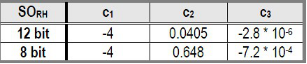
Table 6 Humidity conversion coefficients Table 7 Temperature compensation coefficient
The humidity sensor has no significant voltage dependency
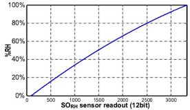
Figure 10 Conversion from SORH to relative humidity
3.1.1 Humidity Sensor RH/Temperature compensation
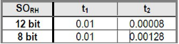
For temperatures significantly different from 25 °C (~77 °F) the temperature coefficient of the RH sensor should be considered:
RHtrue = (T°C - 25)•(t1 +t2 •SORH)+RHlinear
3.2 Temperature
The bandgap PTAT (Proportional To Absolute Temperature) temperature sensor is very linear by design. Use the following formula to convert from digital readout to
temperature:
Temperatur e = d1 +d2 •SOT
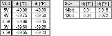
Table 8 Temperature conversion coefficients
For improved accuracies in extreme temperatures with more computation intense conversion formulas see application note “RH and Temperature Non-Linearity Compensation
3.3 Dewpoint
Since humidity and temperature are both measured on the same monolithic chip, the SHTxx allows superb dewpoint measurements. See application note “Dewpoint calculation” for more.
4 Applications Information
4.1 Operating and Storage Conditions
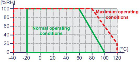
Figure 11 Recommended operating conditions
Conditions outside the recommended range may temporarily offset the RH signal up to ±3 %RH. After return to normal conditions it will slowly return towards calibration state by itself. See 4.3 “Reconditioning Procedure” to accelerate this process. Prolonged exposure to extreme conditions may accelerate ageing.
4.2 Exposure to Chemicals
Chemical vapors may interfere with the polymer layers used for capacitive humidity sensors. The diffusion of chemicals into the polymer may cause a shift in both offset and sensitivity. In a clean environment the contaminants will slowly outgas. The reconditioning procedure described below will accelerate this process. High levels of pollutants may cause permanent damage to the sensing polymer.
4.3 Reconditioning Procedure
The following reconditioning procedure will bring the sensor back to calibration state after exposure to extreme conditions or chemical vapors. 80-90 °C (176-194°F) at < 5 %RH for 24h (baking) followed by 20-30 °C (70-90°F) at > 74 %RH for 48h (re-hydration)
4.4 Temperature Effects
The relative humidity of a gas strongly depends on its temperature. It is therefore essential to keep humidity sensors at the same temperature as the air of which the
relative humidity is to be measured.
If the SHTxx shares a PCB with electronic components that give off heat it should be mounted far away and below the heat source and the housing must remain well ventilated. To reduce heat conduction copper layers between the SHT1x and the rest of the PCB should be minimized and aslit may be milled in between (see figure 13).
4.5 Membranes
A membrane may be used to prevent dirt from entering the housing and to protect the sensor. It will also reduce peak concentrations of chemical vapors. For optimal response times air volume behind the membrane must be kept to a minimum. For the SHT1x package Sensirion recommends the SF1 filter cap for optimal IP67 protection.
4.6 Light
The SHTxx is not light sensitive. Prolonged direct exposure to sunshine or strong UV radiation may age the housing.
4.7 Materials Used for Sealing / Mounting
Many materials absorb humidity and will act as a buffer, increasing response times and hysteresis. Materials in the vicinity of the sensor must therefore be carefully chosen.
Recommended materials are: All Metals, LCP, POM (Delrin), PTFE (Teflon), PE, PEEK, PP, PB, PPS, PSU, PVDF, PVF For sealing and gluing (use sparingly): High filled epoxy for electronic packaging (e.g. glob top, underfill), and Silicone. Outgassing of these materials may also contaminate the SHTxx (cf. 4.2). Store well ventilated after manufacturing or bake at 50°C for 24h to outgas contaminants before packing.
4.8 Wiring Considerations and Signal Integrity
Carrying the SCK and DATA signal parallel and in close proximity (e.g. in wires) for more than 10cm may result in cross talk and loss of communication. This may be resolved by routing VDD and/or GND between the two data signals. Please see the application note “ESD, Latchup and EMC” for more information. Power supply pins (VDD, GND) should be decoupled with a 100 nF capacitor if wires are used.
4.9 ESD (Electrostatic Discharge)
ESD immunity is qualified according to MIL STD 883E, method 3015 (Human Body Model at ±2 kV)). Latch-up immunity is provided at a force current of ±100 mA with Tamb = 80 °C according to JEDEC 17. See application note “ESD, Latchup and EMC” for more information.
5 Important Notices
5.1 Warning, personal injury
Do not use this product as safety or emergency stop devices or in any other application where failure of the product could result in personal injury. Failure to
comply with these instructions could result in death or serious injury. Should buyer purchase or use SENSIRION AG products for any such unintended or unauthorized application, Buyer shall indemnify and hold SENSIRION AG and its officers, employees, subsidiaries, affiliates and distributors harmless against all claims, costs, damages and expenses, and reasonable attorney fees arising out of, directly or indirectly, any claim of personal injury or death associated with such unintended or unauthorized use, even if such claim alleges that SENSIRION AG was negligent regarding the design or manufacture of the part.
5.2 ESD Precautions
The inherent design of this component causes it to be sensitive to electrostatic discharge (ESD). To prevent ESD-induced damage and/or degradation, take normal ESD precautions when handling this product. See application note “ESD, Latchup and EMC” for moreinformation.
5.3 Warranty
SENSIRION AG makes no warranty, representation or guarantee regarding the suitability of its product for any particular purpose, nor does SENSIRION AG assume any liability arising out of the application or use of any product or circuit and specifically disclaims any and all liability, including without limitation consequential or incidental damages. “Typical” parameters can and do vary in different applications. All operating parameters,including “Typical” must be validated for each customer applications by customer’s technical experts. SENSIRION AG reserves the right, without further notice, to change the product specifications and/or information in this
document and to improve reliability, functions and design.
数字温湿度传感器(SHT 1x/ SHT 7x)
_ 相对湿度和温度测量
 _ 兼有露点
_ 全标定输出,无需标定即可互换使用
_ 卓越的长期稳定性
_ 两线制数字接口,无需额外部件
_ 基于请求式测量,因此低能耗
_ 表面贴片或4 针引脚安装
_ 超小尺寸
_ 自动休眠
