摘 要
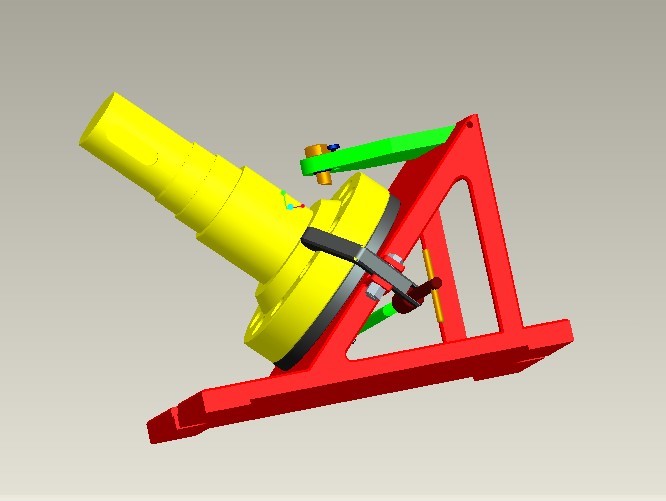
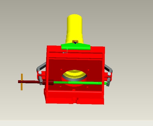
输出轴是主要的动力输出装置,它是输出动力的主要零件。它能够传递转矩,使主轴获得旋转的动力,也正因为如此它要承受较大的扭矩和冲击载荷。因此,该零件需具有足够的耐磨性和抗扭的效果。本设分析了输出轴的各个加工难点、生产类型,根据零件的结构来对毛坯设计、同时也设计了工艺过程。设计了各个加工工序的工装夹具来提高效率,对十字孔的夹具进行了详细的理解分析,分列了一些在操作中可能遇到的实际问题和处理方法。
本文的研究内容是通过分析输出轴零件图,熟练地应用用PRO/E或UG设计夹具,确定装夹方案,并将工件及夹具装配;粗略地计算定位误差与夹紧力,确定工艺路线并编制工艺卡片;绘制工装夹具图。
关键词:输出轴;加工工序;工艺设计;夹具设计
Abstract
The output shaft is the main power output device,which is the main part of the output power. It can transfer torque and give the spindle the power to rotate,and that's why it has to withstand a lot of torque and impact loads. Therefore,the part needs to have sufficient wear resistance and torsion resistance. This paper analyzes the manufacturing difficulties and production types of the output shaft,and designs the blank and the process according to the structure of the parts. the tooling fixture of each processing process is designed to improve the efficiency. the fixture of the cross hole is analyzed in detail,and some practical problems and treatment methods that may be encountered in the operation are classified.
The research content of this paper is to analyze the output shaft part drawing,skillfully apply the design fixture with PRO/E or UG,determine the clamping scheme,and assemble the workpiece and fixture;roughly calculate the positioning error and clamping force,determine the process route and compile the process card;draw the tooling fixture diagram.
Keywords: output shaft;machining process;process design;fixture design
目 录
摘 要 I
Abstract II
第一章 绪论 1
1.1选题依据及意义 1
1.2研究现状 1
1.3研究主要内容 2
第二章 输出轴工艺设计 3
2.1零件图的分析、研究 3
2.2零件性能、用途、工作条件及所在部件中的作用 3
2.3零件材料及其力学性能,选择毛坯种类和制造方法,以及确定切削用量,加工方法 4
2.4分析零件图上各项技术要求制订的依据,确定主要加工表面和次要表面,找出关键技术问题 4
2.5分析零件结构的工艺性 4
第三章 毛坯制造方式 5
3.1确定毛坯种类及加工方式 5
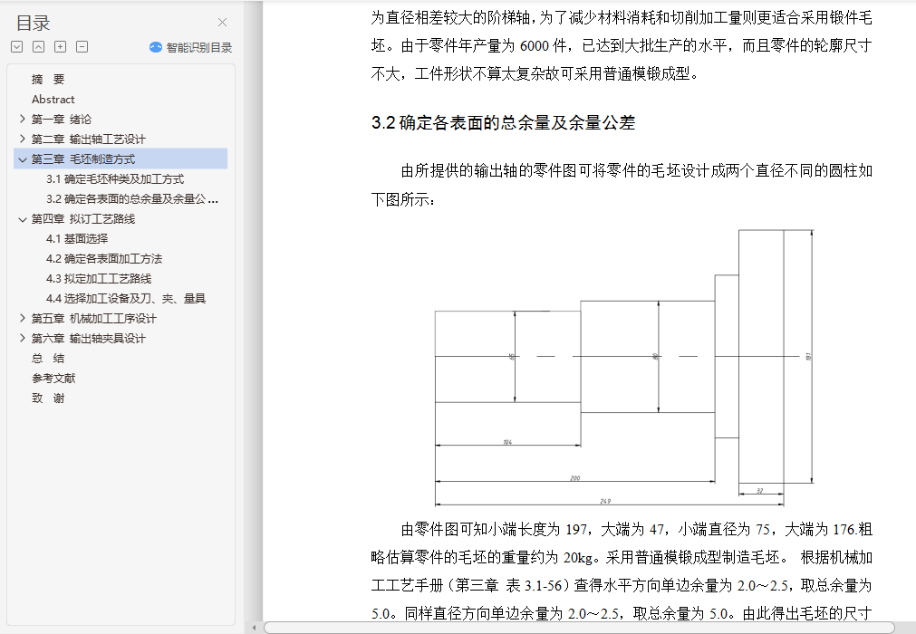
3.2确定各表面的总余量及余量公差 5
第四章 拟订工艺路线 6
4.1基面选择 6
4.2确定各表面加工方法 6
4.3拟定加工工艺路线 7
4.4选择加工设备及刀、夹、量具 9
第五章 机械加工工序设计 11
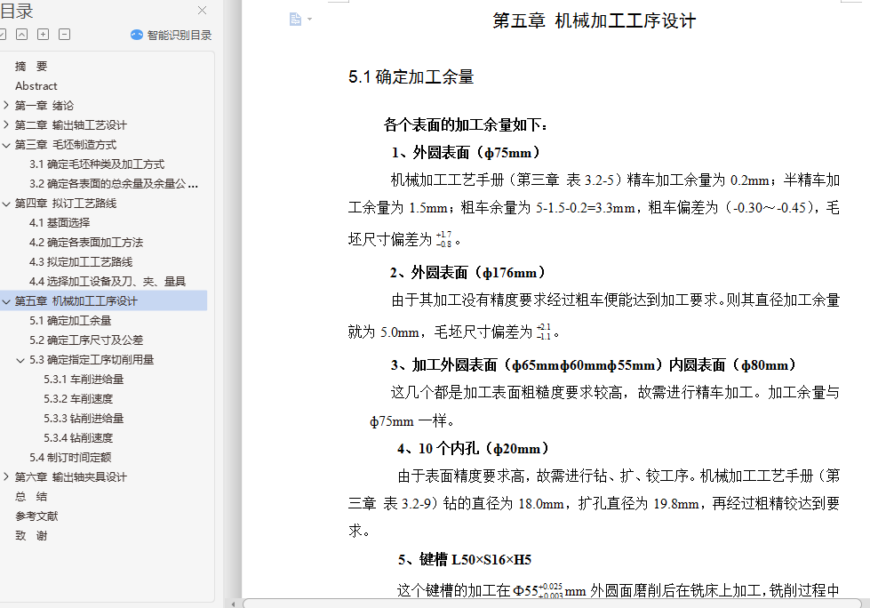
5.1确定加工余量 11
5.2确定工序尺寸及公差 11
5.3确定指定工序切削用量 14
5.3.1车削进给量 14
5.3.2车削速度 14
5.3.3钻削进给量 15
5.3.4钻削速度 16
5.4制订时间定额 16
第六章 输出轴夹具设计 17
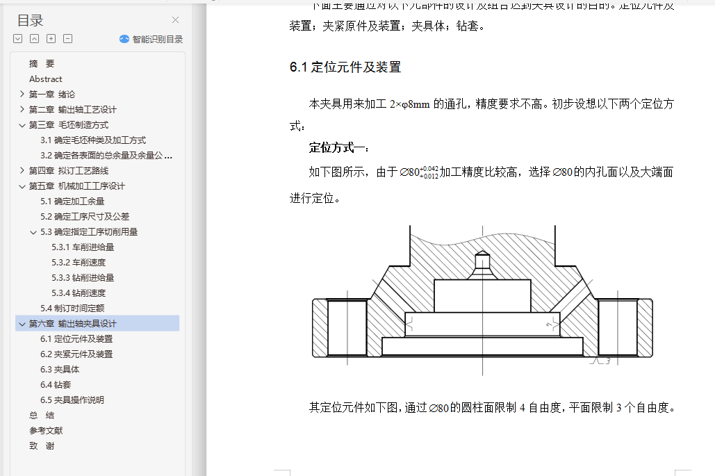
6.1定位元件及装置 17
6.2夹紧元件及装置 19
6.3夹具体 20
6.4钻套 21
6.5夹具操作说明 22
总 结 23
参考文献 24
致 谢 25
