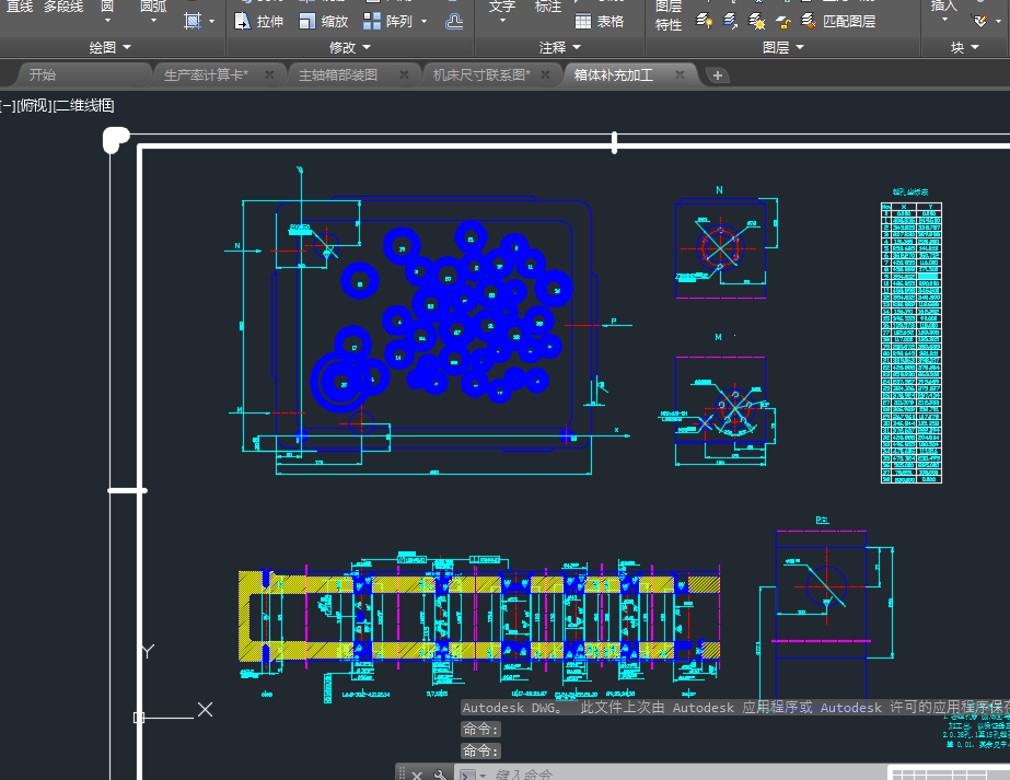
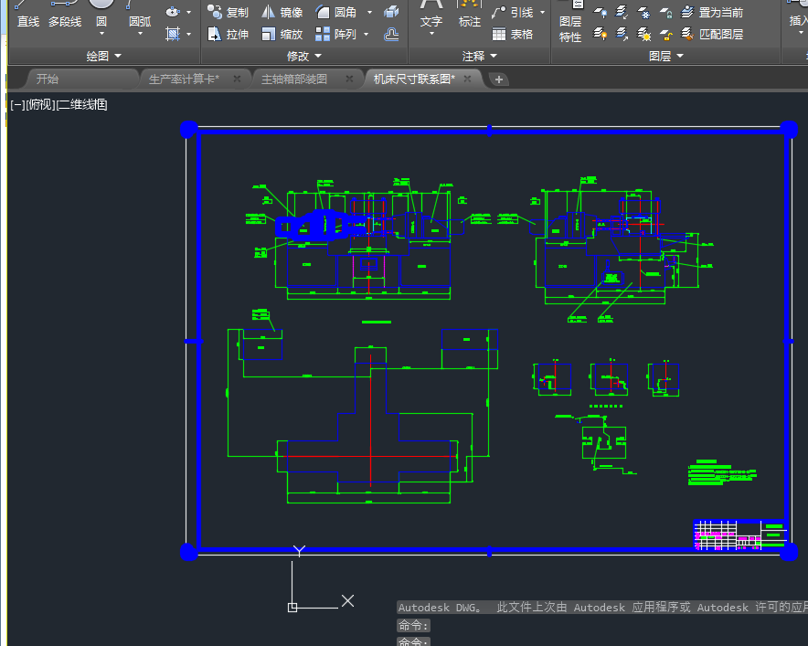
摘 要
本组合机床是针对ZH1105柴油机汽缸体三面攻螺纹组合机床而设计的。在设计中,借鉴了国内外一些现有组合机床资料,结合被加工零件的结构特征,在江淮动力集团现有机床的基础上改进而成的。因为工艺方案在很大程度上决定组合机床的结构配置和实用性能。因此应根据被加工工件的特点,按组合机床常用的设计方法、充分考虑各种影响因素,并分析后拟订出可靠的工艺方案。
在主轴箱设计方面,原有机床采用的是单孔攻丝,加工效率低,孔的加工尺寸不容易保证,且位置精度不高。改进后,将单孔加工改为一次加工,不仅提高了加工效率,而且保证了孔的加工精度问题。
关键词: 组合机床 工艺方案 加工精度
Abstract
The main introduction ZH1105 diesel engine air cylinder three offend the design of the thread combination machine bed, stud. Have refered to some domestic and international existing information of modular machine tool in this designing , combination had been processed the structural feature of element in JiangHuai power inc. Existing machine tool , because of the technology scheme decide practicality and the structural disposition of modular machine tool greatly, so that should according to the characteristic of workpiece, use frequently according to modular machine tool design method , consider various influencing factors fully, after analyse and draw up reliable technology scheme.
In the aspect of main shaft case design, original machine tool adopt is single hole tapping, the processing efficiency is low ,and the processing size of hole can not be guaranteed easily, and the processing efficiency of location precision is also low . After improving, the single hole processing will alter for one processing, have not only raised , have also guaranteed the processing precision problem of hole.
Key words: Combination machine bed; Technology scheme;
Processing precision
目 录
0.前言………………………………………………………………………………1
1. 整体方案论证 ………………………………………………………………… 4
1.1 工艺方案拟订 ………………………………………………………………… 4
1.1.1 卧式组合机床 ……………………………………………………………… 4
1.1.2 立式组合机床 ……………………………………………………………… 4
1.2 绘制三图一卡 ……………………………………………………………… 4
1.2.1 绘制加工工序图 …………………………………………………………… 4
1.2.2 绘制加工示意图 …………………………………………………………… 5
1.2.3 绘制机床总图 ……………………………………………………………… 5
1.3 切削用量的选择 ……………………………………………………………… 5
2. 主轴箱设计 ……………………………………………………………………11
2.1 动力箱选择 ……………………………………………………………………11
2.2 主轴箱传动设计 ………………………………………………………………12
2.2.1 对主轴箱传动系统的一般要求 ……………………………………………12
2.2.2 拟订主轴箱传动系统的基本方法 …………………………………………12
2.2.3 绘制传动树行图 ……………………………………………………………14
2.2.4 确定各轴位置 ………………………………………………………………14
2.2.5 主轴箱坐标计算 ……………………………………………………………15
2.2.6 绘制坐标检查图 ……………………………………………………………17
3. 轴、齿轮校核 …………………………………………………………………18
3.1 轴的校核 ………………………………………………………………18
3.2 齿轮的校核 ……………………………………………………………………18
3.2.1 设计原则 ……………………………………………………………………18
3.2.2 按齿面疲劳强度设计 ………………………………………………………18
3.2.3 计算几何尺寸 ………………………………………………………………20
3.2.4 校核齿根弯曲疲劳强度 ………………………………………20
4. 附件的选择 …………………………………………………………………21
4.1 选用滑台传动形式 ……………………………………………………………21
4.2 选择接杆、浮动卡头 ……………………………………………………… 21
4.3 机床装料高度、夹具轮廓尺寸、中间底座尺寸的确定 ……………………21
5.零部件的设计 ………………………………………………………………21
5.1 绘制主轴箱装配图、靠模体及零件图 ………………………………………22
5.2 绘制主轴箱体前、后盖图 ……………………………………………………22
6. 样机试验测试 …………………………………………………………………23
6.1 组合机床空运转试验 …………………………………………………………23
6.1.1 样机试验要求 ………………………………………………………………23
6.1.2 样机试验结果 ………………………………………………………………23
6.2 组合机床切削试验 ……………………………………………………………23
6.2.1 组合机床试验过程 …………………………………………………………23
6.2.2组合机床试验过程……………………………………………………………23
6.2.3精度测试………………………………………………………………………23
7. 结论 ………………………………………………………………………24
工作小结和致谢 …………………………………………………………25
参考文献 …………………………………………………………………………26
附件清单 ……………………………………………………………………………27


