摘 要
连杆是汽车发动机主要的传动构件之一,把作用于活塞顶部的膨胀气体压力传给曲轴,使活塞的往复直线运动变为曲轴的回转运动,以输出功率。连杆大头孔套在曲轴的连杆轴颈上,与曲轴相连,内装有轴瓦。为了便于安装,大头设计成两半,然后用连杆螺栓连接。连杆小头与活塞销相连,小头压入耐磨的钢衬套,孔内没有油槽,小孔部有油孔,以便使曲轴转动时飞溅的润滑油能流到活塞销的表面上,起润滑作用。
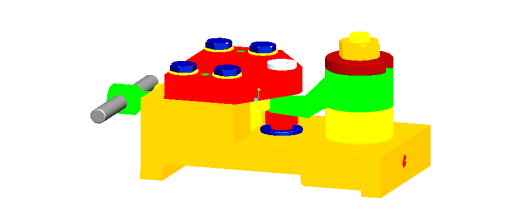
本次毕业设计了解汽车发动机连杆的主要功用,绘出零件图,对零件进行工艺分析,决定毛坯种类和制造方法,拟定大批量生产时机械加工工艺路线,选择各工序设备与工艺装备,确定各工序的尺寸、切削用量及工时定额,填写工艺文件,并设计镗孔夹具一套(含装配图、零件图、三维及仿真设计),撰写设计说明书。
关键词:汽车;发动机;连杆;加工;镗孔夹具
Abstract
Connecting rod is one of the main transmission components of automobile engine. The expanding gas pressure acting on the top of piston is transmitted to the crankshaft so that the reciprocating linear motion of the piston can be changed into the rotary motion of the crankshaft in order to output the power. Connecting rod large head hole sleeve on connecting rod journal of crankshaft,connected with crankshaft, with bearing inside. For ease of installation,the head is designed in half and then bolted with a connecting rod. The small end of the connecting rod is connected with the piston pin, the small head is pressed into the wear-resistant steel bushing,there is no oil groove in the hole, and there are oil holes in the small hole,so that the spattered lubricating oil can flow to the surface of the piston pin when the crankshaft rotates and acts as lubrication.
This graduation design understands the main function of automobile engine connecting rod,draws the part drawing,carries on the craft analysis to the part, decides the blank type and the manufacture method,draws up the mechanical processing craft route in the mass production. Select each process equipment and process equipment, determine the size, cutting amount and man-hour quota of each process,fill in the process document,design a set of boring fixture (including assembly drawing, part drawing, three-dimensional and simulation design), write the design instruction.
Key words: automobile;engine;connecting rod;machining;boring jig
目 录
摘 要 I
Abstract II
第一章 绪论 1
1.1选题背景及意义 1
1.2夹具设计现状 1
1.3设计要求 2
第二章 零件的工艺分析 3
2.1零件的结构特点 3
2.2 零件的技术要求 4
第三章 工艺规程设计 6
3.1 确定毛坯的制造形式 6
3.2基面的选择 6
3.2.1粗基准的选择 8
3.2.2 精基准的选择 8
3.3 制定工艺路线 9
3.4 机械加工余量、工序尺寸及毛坯尺寸的确定 13
3.5确定切削用量及基本工时 15
3.6 切削液的选择 29
第四章 夹具设计 31
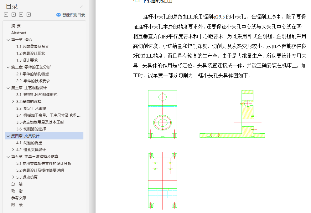
4.1 问题的提出 31
4.2 镗孔夹具设计 32
4.2.1 定位基准的选择 32
4.2.2 切削力及夹紧力的计算 32
4.2.3 定位误差分析 33
第五章 夹具三维建模及仿真 34
5.1专用夹具相关零件的设计分析 34
5.2夹具设计及操作简要说明 37
5.3运动仿真 38
5.3.1 Proe的概述 38
5.3.2运动仿真与分析 38
5.3.3专用镗孔夹具装配运动仿真 39
总 结 43
致 谢 44
参考文献 45
