Route Identification and Direction Control of Smart Car Based on CMOS Image Sensor
Abstract
This paper is designed for the 2nd Freescale Cup National Undergraduate Smart Car Competition. With MC9S12DG128 single chip and smart car model supplied by the committee, a CMOS image sensor is applied to detect the black track on white raceway, which extends the detection range and is helpful to predict the forward path. In this paper, ten-line pixels in an image are analyzed to locate the black track, and the PD algorithm based on PID is employed to control the direction and angle of the steering gear respectively. By repeated testing, the smart car can run stably on the given raceway at a high speed.
Keywords: route identification, direction control, smart car, MC9S12DG128 single chip, image sensor, PID
algorithm.
1. Introduction
The rules of 2nd Freescale Cup National Undergraduate Smart Car Competition [1] may be summarized as follows: the raceway consists of a lot of white boards on which a black track is attached; the smart car designed by participants runs along the black track;every car runs two circles in this game and the best times of two circles will be the final score of this car, and apparently the team whose car takes the best times will bear the palm. According to the rules, we should ensure that the car can distinguish the black track from white board in order to make the smart car run stably. There are two common methods for route identification: one is using infrared diode as the sensor, and another is using CCD/CMOS image sensor [2]. This paper using CMOS image sensor as route identification sensor, the reasons for which are as follows: (1) The range which is covered by a infrared diode sensor is much smaller than a CMOS image sensor covers, and only we can do is to use several diode sensors, but the maximum number of diode sensors used in the smart car is 16; (2) The working voltage of a CMOS image sensor(3.3V) is less than a CCD(12V) or 16 infrared diodes. Apparently, using CMOS image sensor can not only reduce the power consumption but also extend the visible range of the smart car, and also enable the car to predict the forward path. This paper presents a systemic solution for identifying the raceway and controlling the direction of smart car.
2. CMOS camera
There are several kinds of CMOS image sensors in the market. In comparison with other CMOS image sensors, the OV6130 CMOS image sensor [3] made by OmniVision Technologies Inc. is the best choice for us to design a CMOS camera for smart car whether from the viewpoint of cost and performance or power consumption. The OV6130 is a black and white sensor which has a 1/4 inch CMOS imaging device containing approximately 101,376 pixels (352×288). This sensor includes a 356×292 resolution image array, an analog signal processor, dual 8-bit A/D converters, analog video multiplexer, digital data formatter, video port, SCCB interface, registers, and digital controls that include timing block, exposure control, black level control, and white balance.By assembling the experimental circuit we test the OV6130 output ports timing (VSYNC, FODD, HERF). Figure 1 shows the experimental timing diagrams. 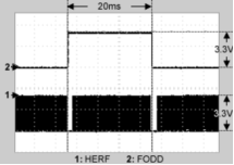
(a) VSYNC-FODD timing
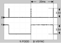
(b) FODD-HERF timing
Figure 1 OV6130 experimental timing diagrams
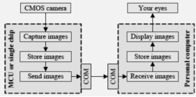
Figure 2 Structure of the image capturing and displaying system
Referring to the OV6130 datasheet, these timing diagrams match well with those given in datasheet, thus we produce the OV6130 CMOS camera based on the experimental circuit. In order to check whether the images captured by camera have clear definition and sharp contrast or not, and also to confirm the visible range of the camera, we design a VB program for capturing the images and displaying them on computer screen. This program bases on three hardware devices: CMOS camera, MCU or single chip, PC. Figure 2 presents how these three devices work together.
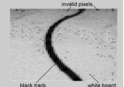
Figure 3 compares the original image of a snake line of raceway with the image captured by CMOS camera and then displayed on screen by VB program. It can be seen that the captured image has clear definition and sharp contrast, and this lays a foundation for route identification to be discussed later.
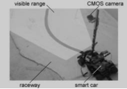
(a) Smart car ready to scan the raceway
(b) Captured image by CMOS camera
Figure 3 Comparison between original image and captured image
3. Route identification
Route identification aims at helping the smart car to recognize the forward track by a method which picks up the black line from the image captured by CMOS camera,and in fact, this method works well in the following cases:straight line, curving line and snake line. By repeated testing, we decide to analyze 10 lines of a whole image to predict the forward condition of smart car. Figure 4 illustrates how we analyze the 10-line pixels of an image.
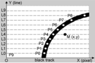
Figure 4 Route identification diagram
The detailed algorithm is introduced as follows:
Step 1: Calculate coordinates of the black pixel for each line ready to be analyzed. As is illustrated in figure 4, the lines (L0, L1, …, L8, L9) are to be analyzed, and the white points (P0, P1, …, P8, P9) are black pixels for each line. The origin O is superposed by P9, which means there is no black pixel in line L9. Assumed that P(x) and P(y) indicate x-coordinate and y-coordinate of point P,respectively, here both P9(x) and P9(y) equal 0.The key of this step is to find the black pixel of each line. Here, by taking the following datum which shows the gray values of all pixels in a line as example, we introduce
a new approach:
195 210 207 215 208 228 236 243 238 234 238 235 231 233 230 235 230 222 196 207 204 208 209 129 160 65 17 15 19 18 79 151 172 153 173 150 147 159 141 153 147 154 137 139 156 136 141 9 141 133 138 4 127 110 141 112 104
(1) Assumed that P is the black pixel of this line, G(i)denotes a pixel and i indicates it’s position in this line, V(i) is the gray value of G(i), j is the position of the first black pixel appearing in the line from left to right. Here both P(x) and P(y) are initiated to 0, and j is 0 from the start.
(2) As for each pixel in this line from left to right,comparing its gray value with the black value B, here we set B as 30, G(i) is a black pixel on condition that V(i) is less than B. In the line above, the pixels underlined in bold, whose gray values are 17,15,16,18, are component points of the black track, and the pixels underlined both in bold and italic, whose gray values are 9,4, are invalid or interferential pixels. If V(i) is less than B, set j as i. Then compare V(j+1) and V(j+2) with B respectively, results go to two sides: ① If both V(j+1) and V(j+2) are less than B, check the gray value for each pixel from G(j+3) to the end pixel of this line. If the total number of white pixels whose gray values are greater than B surpasses or equals to 3, then set P as G(j+1). Otherwise, go to (3); ② If not, repeat this way from the point G(j+3) on.
(3) If there is no black pixel in this line, set both P(x) and P(y) as 0.
Step 2: Calculate the average coordinates of 10 black pixels. As is showed in Figure 4, M is the average point, M(x) and M(y) are expressed as follows:
Step 3: According to the position of M in the image,we can decide in which direction (ahead, left, or right) the smart car should turn. In Figure 4, the smart car should turn right obviously.
Step 4: Calculate how many angles the car should turn.Further descriptions is illustrated in Figure 5, where α is the very angle by which the car should turn right, F is the central point of two front wheels, M is the average point mentioned previously (see Figure 4), D and L1 indicate the width and height of the visible range of CMOS camera respectively, L2 is the distance between visible range and front wheels, L3 is a half of front wheel’s diameter, L2+L3 means the distance between visible range and the axis of front wheels. Referring to Figure 5, it is very easy to calculate the angle α.
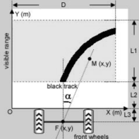
Figure 5 Calculating the angle for turning
4. Direction control
The central unit for direction control of smart car is steering gear, its input signal is PWM (Pulse-Width Modulation) pulse, and it outputs corresponding angle in radian. This paper uses the PWM output port of MC9S12DG128 single chip [4] as the input signal of steering gear. By inputting the given discrete width of pulse, we test the relationship between the input and the output. The formula below expresses it:
where X is tangential value of the output angle, Y is width of the input pulse, y0 is the corresponding value when the output angel equals 0 and k is slope. Using this linear relationship we can operate the smart car simply just by inputting the target angel, thus the width of pulse which is the input signal of steering gear can be computed easily,this method, however, doesn’t work well in the following cases: curving line and snake track. Therefore we apply the PID [5] (Proportional, Integral, and Differential) controller which is very popular in fields of automation and control technology. The kernel theory of PID is to do proportional, integral and differential operations on the input difference respectively, then join the three results as the final output value. In practice, it is very flexible for us to use according to features and demands of the object to be controlled. We may choose one or two or all of PID modules, for example, we can use proportional and integral modules to make up of PI controller.As for the smart car, it is no necessary to consider the tracks which have been gone across, so we only use proportional and differential modules as PD adjuster, and P adjuster has been described previously (see Formula(2)), and the following formula shows the D adjuster:
where enew , eold define the differences of this time and last time when the angle is computed (here difference means the angel by which the steering gear should turn), t is scanning period of CMOS camera, kd is differential coefficient which runs from 0.5 to 1.5, D_out is the output of D adjuster.
5. Conclusions
The challenge of this work is a systemic solution for identifying the black route and controlling the direction of smart car. The performance of CMOS camera is apparently superior to infrared diode whether in scanning range or whether in power consumption, and the clear definition and sharp contrast of image are also important for the further recognition and control. By repeated testing, it is proved that the PD adjuster works well when
the car runs whether on curving line or on snake track at a high speed, and the stability of smart car is also promoted.


